High Speed Motor Control
Overview
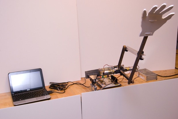
The project suggested was to design a system for high speed motor control using the PIC 32. To demonstrate the motor control, a two degree of freedom (2-DOF) parallelogram robot arm was designed to follow paths specified in a MATLAB gui.
Team Members

- Sam Bobb (Electrical Engineering senior, left)
- Daniel Cornew (Mechanical Engineering junior, right)
- Ryan Deeter (Mechanical Engineering junior, middle)
Mechanical Design
Theory of Parallelogram Design
Equations of Motion
Commanding the arm is much easier for a user to do in x- and y- coordinates than in motor angles or encoder counts. Therefore, equations were required that would translate x- and y- coordinates into angles from horizontal and then into encoder counts. Equations to express the reverse (encoder counts to angles to x- and y- coordinates) were also needed to evaluate the accuracy of the execution with respect to the command path. These equations were found on this helpful website. The following block of MATLAB code shows how these equations were adapted for this project.
function [ x, y ] = arm_thetas_to_xy( theta1, theta2 )
%ARM_THETAS_TO_XY Uses forward kinematics to give position from angle
%   Pass in theta1 and theta2 (in degrees)
%   Returns x and y
%   ---
%   Sam Bobb,  Daniel Cornew,  Ryan Deeter
%	Two degree of freedom arm
%	High speed motor control for 2 motors
%	Code version 3
%	March 18, 2010
%   ---

% pull in constants
arm_constants

alpha = deg2rad(theta1);
psi = deg2rad(theta2 - theta1);

j1_x = L1*cos(alpha);
j1_y = L1*sin(alpha);

j2_x = L2*cos(alpha+psi) + j1_x;
j2_y = L2*sin(alpha+psi) + j1_y;

x = j2_x;
y = j2_y;

end
function [ theta1, theta2 ] = arm_xy_to_thetas( x, y )
%ARM_XY_TO_THETAS Uses inversion kinematics to give angles for position
%   Pass in x and y
%   Returns theta1 and theta2 (in degrees)
%   ---
%   Sam Bobb,  Daniel Cornew,  Ryan Deeter
%	Two degree of freedom arm
%	High speed motor control for 2 motors
%	Code version 3
%	March 18, 2010
%   ---

% pull in constants
arm_constants

% calculate the theta path
c2 = (x.^2 + y.^2 - L1.^2 - L2.^2) / (2 * L1 * L2);
s2 = sqrt(1 - c2.^2);
psi = acos((x.^2 + y.^2 - L1^2 - L2^2) / (2 * L1 * L2));
alpha = asin((y .* (L1 + L2 .* c2) - x .* L2 .* s2) ./ (x.^2 + y.^2));

% convert to degrees
theta1 = rad2deg(alpha);
theta2 = rad2deg(alpha+psi);

end
Materials and Construction
The Motors are mounted into right-angle pieces of aluminum via screws in the face-plate of the motors. Each right angle has a slot milled into its base, and there is a flat aluminum base that also has a slot milled into it. The right angles are secured to this base with bolts, nuts, and lock washers. This slotted construction allows the position of the motors to be adjusted in order to ensure free movement of the arms.
Attached to each motor is a carbon fiber arm. These arms are 1/2 inch thick carbon-nomex-carbon layups. (Nomex is a material that provides rigidity to carbon fiber.) Each arm has an aluminum block with a hole and set screw for mounting epoxied to one end. One of these carbon fiber arms has a bearing mounted in it 10 inches away from the motor shaft, and the other has a pin mounted at the same distance.
There are two other component to the parallelogram assembly. One is a 22 inch by 1/2 inch length of carbon-nomex-carbon. This piece has one pin mounted 1 inch away from one end, and another pin mounted 10 inches away from that. The other piece is a 12 inch long piece of aluminum that has been bent into a 1 inch by in inch U-shape. This piece has two ball-bearing epoxied into it 10 inches apart.
The longer piece of carbon has the pin closest to its end press fit into the ball bearing mounted into the motor arm. The U-shaped piece of aluminum has on ball bearing slid onto the other motor arm, and secured with a snap ring. The remaining ball bearing is then slid onto the reaming pin in the long piece of carbon and secured with a snap ring.
The position of the motors relative to one another in then adjusted unit the arms move freely, and then fastened in place.
Electrical Design
Overview


Electronics consist of decoder circuits for the encoders on each motor, an H-bridge circuit for each motor connected to a PWM output on the PIC and two digital IO pins for direction, the serial cable connection to the PC, LEDs for error alerts, and optical break sensors to measure the absolute position of the arm.
The quadrature output from the motors is decoded and sent to the PIC with the LS7083 chip. A 332 kilo-ohm resistor provides an appropriate pulse output width.
Each motor is driven by one L298 dual H-bridge package. This package contains two H-bridges which are connected in parallel to increase the current handling ability. It is important to connect parallel the two H-bridges within the chip in exactly the way shown in the diagram. Heat sinks are required on these chips. High speed fly-back diodes are required to protect the H-bridge chips. Schottkey diodes were used because they provide almost instant reverse recovery time.
Components
| Electrical Components Needed. | Quantity | Data Sheets |
|---|---|---|
| PIC 32 on NU32 board | 1 | Introduction to the PIC32 |
| H-bridges L298 | 2 | data sheet |
| Optoisolators 4N27 | 6 | data sheet |
| Quadrature Up/Down decoders LS7083 | 2 | data sheet |
| QVB11134 Optointerrupters | 2 | data sheet |
| 35V 9A Schottkey Diodes 90SQ035-ND | 8 | data sheet |
| Pittman GM8224 motor with 19.5:1 gearhead and 500 line encoder | 2 | data sheet |
| 24VDC 6A power supply | 1 | N/A |
GUI
The GUI was programmed in MATLAB using the "guide" function. The GUI code calls the other MATLAB functions and is rather small as far as the amount of new code in contains.

Usage
The GUI is made up of four main sections that allow a user to control the path and motor control parameters of the arm and plot the results.
The first section is the "Path" section, which allows users to specify the type of path the arm will follow. There are currently three path choices: "go to," "circle," and "trace." The "go to" path allows the user to specify a point that the arm will go to from its current position in five seconds. The "circle" path is determined through five values. The first two are the (x, y) of the center of the circle. The next two are coefficients on sin and cosine terms that are effectively the radii. The last value is the time in seconds for the arm to complete the circle. In the final path, "trace," users input four (x, y) positions and the arm moves from the first to the fourth and back to the first with two seconds in between points. The GUI could easily be changed so that the user specifies (x, y, t) and controls the time between points, but this would require velocity-based failure checking in the code to ensure that the user did not give a command that was dangerous to the arm.
The section just to the right of the "Path" section allows for further manipulation of the path and motor control. A checkbox controls whether or not the specified path loops (note: "go to" cannot loop). Beneath the checkbox is a section labeled "PID Control" and it lets users adjust the coefficients kp (proportional), ki (integral) and kd (derivative) on the fly by pressing the "Update" button.
The section on the far right is used to communicate between MATLAB and the PIC. A COM port is specified for communication. The "Connect" button opens the COM port, and the "Disconnect" button closes it. The "Start" button runs whichever path is specified in the "Path" section, and "Pause" pauses the path (note: to unpause, click the "Start" button again while paused).
The final section of the GUI is the "Graphs" section. This section plots the path of the arm in either "theta vs t" or "x vs y," as selected by the radio buttons. Plotted in the dark color is the path that the PIC tried to execute, and the light color plot shows the actual path of the arm, for comparison. Currently, the plotting commands are buggy. Data only plot if "Continuous Update" is on, and the "Get Data" button does not seem to function. The problem here is communicating between the GUI and the other MATLAB functions, and this could easily be corrected.
Code
Using MATLAB's "guide" function when creating GUIs makes for rather straightforward coding. When a component is added to the GUI (be it a button, text field, etc.), MATLAB adds a block of code to an automatically generated m-file. These blocks are functions, which means that programming them requires the use of handles. Here is an example:
   function xCoor_Callback(hObject, eventdata, handles)
   % hObject    handle to xCoor (see GCBO)
   % eventdata  reserved - to be defined in a future version of MATLAB
   % handles    structure with handles and user data (see GUIDATA)
   if get(handles.goToButton, 'Value') == 1
       xCoor = get(hObject, 'String');
   end
This block of code is for the x-coordinate of the "Go To" path option. The if statement utilizes handles so that the "Go To" button's function can be accessed from the x-coordinate function. This block sets the x-coordinate of the "Go To" command to the user specified value in the GUI if the "Go To" button is selected.
Code
Overview
There are two main applications: the C code that runs on the PIC and the MATLAB code that runs on a PC. The two applications communicate by sending command packets over a serial connection. The packets consist of a string of 16-bit integers. The first integer identifies the command and the following integers carry the parameters. This table shows the available commands.
| Command | Identifying Integer | Description | Number of following ints | Syntax for following ints |
|---|---|---|---|---|
| C_HOLD | 0 | Hold arm in home position | 2 | [ x_position y_position ] |
| C_FLOAT | 1 | Stop and float motors | 1 | [ true = 1 ] |
| C_RUN | 2 | Run path | 1 | [ true = 1 ] |
| C_CONTROL_CONFIG | 3 | Send new control parameters | 14 | [ KPnum1 KPden1 KDnum1 KDden1 KInum1 KIden1 Kslope1 KPnum2 KPden2 KDnum2 KDden2 KInum2 KIden2 Kslope2 ] |
| C_LOG_CONFIG | 4 | Send new logging parameters (unimplemented) | 0 | -- |
| C_SET_PATH | 5 | Send new path points | variable | [ n time1 theta11 theta21 time2 theta12 theta22 time3 theta13 theta23 ... timen theta1n theta2n ] |
| C_SEND_LOG | 6 | Asks the PIC to send logged data | 0 | -- |
| C_LOOP | 7 | Sets the looping option | 1 | 0 = run once, 1 = loop the path |
| C_STARTSTOP | 8 | start and stop (unimplemented) | 0 | -- |
| C_GOTO | 9 | Tells the arm to goto a certain X,Y | 2 | [ X Y ] |
| C_PAUSE | 10 | Stop and hold at current location | 0 | -- |
For example, the vector that MATLAB sends to move the arm to X = 15, Y = -10 would be: [9 15 -10].
PIC C Code
This code runs on the PIC 32 and handles the motor control, control loop, logging, and serial interface. On start up, the PIC runs the initialization routines, and then waits for the user to move the arm through each of the optical break sensors. When a break is detected on one of the sensors, the position of the corresponding arm is set to zero. This allows an absolute position to be established for each arm. Once the procedure is complete, the PIC waits for commands from the PC.
Initialization
- mInitAllLEDs() -- sets up the on board LEDs
- initPWMandIO() -- sets up digital IO pins for motors and more LEDs, sets up two analog to digital converters for the optical break sensors, configures the PWM modules and assigns them to Timer 3, and configures Timer3 at 20kHz
- initEncoder() -- Sets up Timers 1, 2, 4, and 5 as external counters for the encoders.
- initUART2(pbClk) -- Sets up UART2 for serial communication.
Timed loop (2 kHz)
Every 0.5 ms the control loop runs. This loop updates the current theta values of each motor by reading the encoder counts. It then checks the limits on the arms to make sure they have not gone out of acceptable ranges. Then the new reference thetas are calculated based on the current time and the path points. The reference and current thetas are used to calculate error and then run the PID control which sets the motor outputs. Data is recorded to the log every 20 control loops.
Serial Interrupt
When the PIC receives serial data, the first two bytes are read and assembled into one 16 bit integer. This integer is then matched to the command table to identify the command. For each command, the correct number of extra integers are read from the serial buffer and global variables are filled in to adjust control parameters, path points, and runtime options.
MATLAB Code
The MATLAB library consists of functions for each of the commands that can be sent to the PIC and some helper functions. When one of the callback functions from the GUI runs, it pulls parameters from the interface, assembles them, and passes them to the proper command functions.
Within the arm command functions, MATLAB uses the fwrite function to write data to the serial port. The int16 option ensures that MATLAB breaks each number into a 16 bit integer and sends it as two bytes out the serial port. The PIC will then reassemble these two bytes as a 16 bit integer.
Example MATLAB procedure
Suppose the user wants move the arm to X = 15, Y = -10. The following happens:
- The user opens the GUI by running me333gui from the MATLAB command line
- The user puts the proper COM port in the COM port text box and clicks Connect
- The function Connect_Callback runs. This function pulls the text from COMport text box and sends it to the arm_connect function. The serial port is now open. The handle for the serial port object is stored in the UserData field.
- The user puts the desired X and Y in the goto X and Y text boxes, selects the GoTo radio button, and clicks Start.
- The function startButton_Callback. This function checks which of the mode radio buttons are selected. If GoTo is selected, it reads from the X and Y boxes, and calls the arm_goto function with the COM port handle and the X and Y from the text box.
- The arm receives the command and executes the move.
Results
This video demonstration shows the capabilities of the arm.
Before paths are executed, the arm is lifted manually so that the optointerrupters are tripped and the arm is "homed," meaning that the PIC recognizes the arm's location with respect to motor encoder counts.
The first path executed is a simple "Go To."

After the "Go To," a looped "Trace" path is executed. The GUI screenshot at the right was used to generate this path. The top screenshot shows theta plotted against time and the bottom shows position plotted in xy space.


The last two paths are both circles. The first is a slow, wide circle rotating counter clockwise. The second is a quicker, tighter circle rotating clockwise. The GUI for the wide circle is at the right.
Next Steps
This project came a long way, but could go much further.
One large area of improvement is in the logging of data. Logging speeds could be improved through more efficient coding, but even more through the use of USB communication. Since data are currently sent through RS-232, top transmission speeds are limited. Using USB would allow for the GUI graphs to update in much closer to real time.
The motor control parameters could be tweaked to provide for greater control. Part of that is just trail and error for different constants, but better derivative and integral terms could be used in the control.
Mechanical improvements would also aid in control. The arms currently move about and bounce (as seen in the video) due to motor backlash. Fixing this problem would allow for even more precise, quicker motions.
The GUI could also be greatly improved to allow for more user options. The options were limited in this version to reduce the likelihood that a user would program a path fatal to the arm. With improved software and hardware limit switching, more user control would be available.
Acknowledgements
We would like to acknowledge Professor Lynch, Nick Marchuk and Andy Long for their instruction and guidance throughout this project.