Difference between revisions of "Second Order Active Filters"
StevenManuel (talk | contribs) m (Second Order Filters moved to Second Order Active Filters) |
|||
| (16 intermediate revisions by one other user not shown) | |||
| Line 1: | Line 1: | ||
2nd order active filtering has two main advantages: |
2nd order active filtering has two main advantages: |
||
* High impedance input, low impedance output |
|||
* greater attenuation at high range (-40dB/decade as opposed to -20dB/decade for RC filter) |
|||
The high impedance provided by an op amp circuit protects the instrument providing the signal from passing excessive current which could cause a voltage drop in the measurement signal or damage to the instrument itself. |
The high input impedance provided by an op amp circuit protects the instrument providing the signal from passing excessive current which could cause a voltage drop in the measurement signal or damage to the instrument itself. |
||
Because the filter is second order, the rolloff |
Because the filter is second order, the rolloff after the cutoff frequency on a bode plot of a 2nd order low pass filter for example, is -40 dB/decade as opposed to -20 dB/decade for a first order (RC) filter which means significantly greater attenuation outside the pass band and a sharper cutoff. This can be very useful if the noise frequency is close to the desired signal frequency. |
||
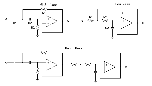
[[Image:2ndOrderFilterDiagrams.gif]] |
|||
(http://ourworld.compuserve.com/homepages/Bill_Bowden/opamp.htm) |
|||
Where the cutoff frequency for both high and low pass filters in Hz is: |
|||
<math>f=1/(2*pi*sqrt(R_1 R_2 C_1 C_2))</math> |
|||
'''External Links''' |
|||
http://en.wikipedia.org/wiki/Sallen_Key_filter |
|||
Latest revision as of 15:45, 14 December 2008
2nd order active filtering has two main advantages:
- High impedance input, low impedance output
- greater attenuation at high range (-40dB/decade as opposed to -20dB/decade for RC filter)
The high input impedance provided by an op amp circuit protects the instrument providing the signal from passing excessive current which could cause a voltage drop in the measurement signal or damage to the instrument itself.
Because the filter is second order, the rolloff after the cutoff frequency on a bode plot of a 2nd order low pass filter for example, is -40 dB/decade as opposed to -20 dB/decade for a first order (RC) filter which means significantly greater attenuation outside the pass band and a sharper cutoff. This can be very useful if the noise frequency is close to the desired signal frequency.
(http://ourworld.compuserve.com/homepages/Bill_Bowden/opamp.htm)
Where the cutoff frequency for both high and low pass filters in Hz is:
External Links

