Difference between revisions of "ProcessingPIC32Communication"
NickMarchuk (talk | contribs) |
NickMarchuk (talk | contribs) |
||
| Line 217: | Line 217: | ||
The following code achieves this: |
The following code achieves this: |
||
< |
<pre> |
||
code |
code |
||
< |
<pre> |
||
Revision as of 08:58, 16 July 2010
Tutorial: Communication between a PIC32 and Processing
This tutorial will demonstrate how to use Processing to communicate with a microcontroller, specifically the UBW32, a PIC32MX460F512L device. An FTDI Serial to USB cable will be used to communicate over USB.
UBW32 Setup
Download and install the latest version of MPLAB (v8.53) here.
Also download and install the C compiler here and Microchip Applications Library (4/28/2010) here if you have never installed MPLAB on your computer.
Download this Media:ubw32_tutorial.zip that has code specific to the UBW32. Unzip it into the directory you will work in today.
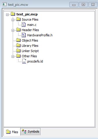
Start a new project in MPLAB and include the files specific to the UBW32. Your project should look like:
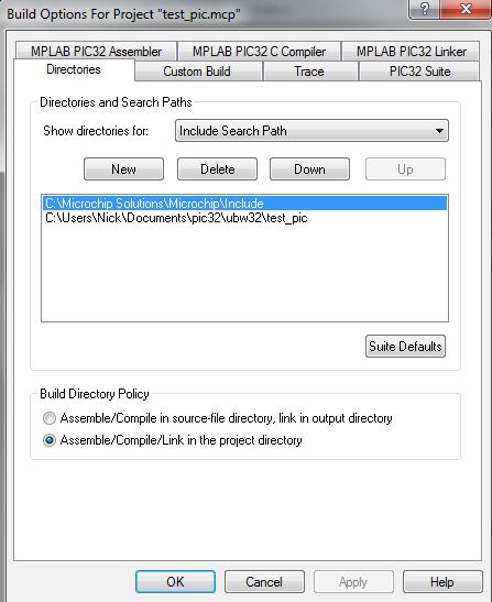
Don't forget to tell the compiler where to find some source files:
We will program the UBW32 to:
- Interrupt when it receives a character over RS232
- Read an analog value and send it over RS232 to the PC
- Change how often it outputs data according to the character it receives
Specifically:
- Initially output at 5Hz
- Output at 10Hz if a "b" is received
- Output at 100Hz if a "c" is received
- Output at 5Hz if a "a" is received
- Stop outputting if a "p" is received
- Start outputting if a "t" is received
- Toggle an LED on the UBW32 board if a "w" is received
The following code achieves this:
#include "GenericTypeDefs.h"
#include "Compiler.h"
#include "HardwareProfile.h"

// NOTE THAT BECAUSE WE USE THE BOOTLOADER, NO CONFIGURATION IS NECESSARY
// THE BOOTLOADER PROJECT ACTUALLY CONTROLS ALL OF OUR CONFIG BITS

#define SYS_FREQ (80000000L)
#define DESIRED_BAUDRATE (115200) // The desired rs232 BaudRate

unsigned short int channel4;	// conversion result as read from result buffer

char UART1_out_buffer[64];
int hz5 = 62500; // 80000000/256/5
int hz10 = 31250; // 80000000/256/10
int hz100 = 3125; // 80000000/256/100

// functions
void init_serial();
void init_analog();
void init_timer(int freq);

int main(void)
{
    // Configure the proper PB frequency and the number of wait states
	SYSTEMConfigPerformance(80000000L);

	// Turn off JTAG so we get the pins back
 	mJTAGPortEnable(0);

    //Initialize all of the LED pins
	mInitAllLEDs();

    // enable multi-vector interrupts
	INTEnableSystemMultiVectoredInt();

	init_serial();
	init_timer(hz10);
	init_analog();

    while(1)
    {
		// empty, interrupt driven code
    }
}

// UART 1 interrupt handler, gets info from processing
// it is set at priority level 1
void __ISR(_UART1_VECTOR, ipl1) IntUart1Handler(void)
{
	char data;
	// Is this an RX interrupt?
	if(mU1RXGetIntFlag())
	{
		// Clear the RX interrupt Flag
	    mU1RXClearIntFlag();

		data = (char) ReadUART1();

		// Echo what we just received.
		//putcUART1(data);

		if (data == 'a'){
			init_timer(hz5);
		}
		else if (data == 'b'){
			init_timer(hz10);
		}
		else if (data == 'c'){
			init_timer(hz100);
		}
		else if (data == 'p'){
			mT3IntEnable(0);
		}
		else if (data == 't'){
			init_timer(hz5);
		}
		else if (data == 'w'){
			mLED_3_Toggle();
		}
	}

	// We don't care about TX interrupt
	if ( mU1TXGetIntFlag() )
	{
		mU1TXClearIntFlag();
	}
} // end UART1 interrupt

// interrput code for the timer 3, priority level 2
void __ISR( _TIMER_3_VECTOR, ipl2) T3Interrupt( void)
{
	// read analog
	channel4 = ReadADC10(0); // read the result of channel 4

	sprintf(UART1_out_buffer,"a %d\r\n",channel4);
	putsUART1(UART1_out_buffer);

	// clear interrupt flag and exit
	mT3ClearIntFlag();
} // end T3 Interrupt

void init_serial() {
	int	pbClk;
	// Configure the system performance
	pbClk = SYSTEMConfigPerformance(SYS_FREQ);

	// define setup Configuration 1 for OpenUARTx
	#define config1 UART_EN | UART_IDLE_CON | UART_RX_TX | UART_DIS_WAKE | UART_DIS_LOOPBACK | UART_DIS_ABAUD | UART_NO_PAR_8BIT | UART_1STOPBIT | UART_IRDA_DIS | UART_DIS_BCLK_CTS_RTS| UART_NORMAL_RX | UART_BRGH_SIXTEEN

	// define setup Configuration 2 for OpenUARTx
	#define config2	UART_TX_PIN_LOW | UART_RX_ENABLE | UART_TX_ENABLE | UART_INT_TX | UART_INT_RX_CHAR | UART_ADR_DETECT_DIS | UART_RX_OVERRUN_CLEAR

    // Open UART1 with config1 and config2
	OpenUART1( config1, config2, pbClk/16/DESIRED_BAUDRATE-1); //U1RX=F2, U1TX=F8

	// Configure UART1 RX Interrupt with priority 1
	ConfigIntUART1(UART_INT_PR1 | UART_RX_INT_EN);
} // end init serial

void init_analog() {
	// configure and enable the ADC
	CloseADC10();	// ensure the ADC is off before setting the configuration

	// define setup parameters for OpenADC10
	// Turn module on | output in integer | trigger mode auto | enable  autosample
	#define PARAM1  ADC_MODULE_ON | ADC_FORMAT_INTG | ADC_CLK_AUTO | ADC_AUTO_SAMPLING_ON

	// define setup parameters for OpenADC10
	// ADC ref external    | disable offset test    | enable scan mode | perform 2 samples | use one buffer | use MUXA mode
	#define PARAM2  ADC_VREF_AVDD_AVSS | ADC_OFFSET_CAL_DISABLE | ADC_SCAN_ON | ADC_SAMPLES_PER_INT_2 | ADC_ALT_BUF_OFF | ADC_ALT_INPUT_OFF

	// define setup parameters for OpenADC10
	// 				  use ADC internal clock | set sample time
	#define PARAM3  ADC_CONV_CLK_INTERNAL_RC | ADC_SAMPLE_TIME_15

	// define setup parameters for OpenADC10
	// set AN4
	#define PARAM4	ENABLE_AN4_ANA

	// define setup parameters for OpenADC10
	// do not assign channels to scan
	#define PARAM5	SKIP_SCAN_AN0 | SKIP_SCAN_AN1 | SKIP_SCAN_AN2 | SKIP_SCAN_AN3 | SKIP_SCAN_AN6 | SKIP_SCAN_AN7 | SKIP_SCAN_AN8 | SKIP_SCAN_AN9 | SKIP_SCAN_AN10 | SKIP_SCAN_AN11 | SKIP_SCAN_AN12 | SKIP_SCAN_AN13 | SKIP_SCAN_AN14 | SKIP_SCAN_AN15

	// use ground as neg ref for A | use AN4 (B4) and AN5(B5) for input A
	// configure to sample AN4
	SetChanADC10( ADC_CH0_NEG_SAMPLEA_NVREF); // configure to sample AN4
	OpenADC10( PARAM1, PARAM2, PARAM3, PARAM4, PARAM5 ); // configure ADC using parameter define above

	EnableADC10(); // Enable the ADC
 	while ( ! mAD1GetIntFlag() ) { } // wait for the first conversion to complete so there will be valid data in ADC result registers
} // end init_analog

void init_timer(int freq) {
	// init Timer3 mode and period (PR3)
	OpenTimer3( T3_ON | T3_PS_1_256 | T3_SOURCE_INT, freq); // 30Hz
	mT3SetIntPriority( 2); 	// set Timer3 Interrupt Priority
	mT3ClearIntFlag(); 		// clear interrupt flag
	mT3IntEnable( 1);		// enable timer3 interrupts
}
Test the UBW32 code
Plug your FTDI cable into your computer and determine its port number (ex COM3). Run HyperTerminal (in XP only) or PuTTY. Open the correct com port and set the baud. Turn on the UBW32. Data should start to stream to the terminal. Type each character programmed and see the effect.
Processing Setup
Download Processing (v1.2.1).
Open Processing and save the blank sketch. This will create a folder for all the files the sketch will use.
Download and extract the controlP5 GUI library for Processing. Put it a folder called "libraries" in the Processing folder of My Documents (the same root directory as the folder that was made when you saved your blank sketch).
The sketch we will make will open the UBW32's virtual serial port and communicate with the UBW32. It will plot the analog values the UBW32 sends and have buttons to stop and start the data, and change the data rate.
The following code achieves this:
code

