Operational Amplifiers (Op-Amps)
Op-amps and transistors are the staples of analog circuit design. Internally, op-amps consist of many transistors, capacitors, and resistors.
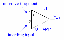
Each op-amp has an inverting input, a non-inverting input, and an output. In practice, op-amps also must be powered and grounded, but since the power and ground won't affect our schematic design, the leads are usually omitted in the drawings.
Op-amps are generally very well described the their ideal model.There are several basic rules for ideal op-amps:
1. There is no voltage difference across the inputs. Although the gain of an ideal op-amp is considered to be infinitely large, the op-amp will try to keep the inputs at the same voltage by somehow sending the output signal back to the input to push or pull the input voltages to the same level.
2. The input current draw is zero. In real op-amps, there will be a small current draw because the op-amp does not have infinite resistance (maybe for FETs and for BJTs).


