Difference between revisions of "NU32v2: Using the LS7183 Quadrature Clock Converter"
Andrew Long (talk | contribs) |
Andrew Long (talk | contribs) |
||
| Line 19: | Line 19: | ||
== Sample Code == |
== Sample Code == |
||
The full code can be downloaded [[Media:NU32v2_Encoder.c | here]]. The code configures 2 external counters (see [[NU32v2: Counters and Timers#External Counter|Counters and Timers]]) that will increment with each pulse received from the LS7183. The |
The full code can be downloaded [[Media:NU32v2_Encoder.c | here]]. The code configures 2 external counters (see [[NU32v2: Counters and Timers#External Counter|Counters and Timers]]) that will increment with each pulse received from the LS7183. The example sends the encoder position via RS232 to your PC. |
||
The main code shown below can be placed in an ISR if you want to read the encoder at a given |
The main piece of code shown below reads the UP and DOWN counters. With a variable called bigcount, it adds the the recent UP counts, subtracts the down counts and adjusts for roll-over of the counters. The full code placed this code in the main while loop, but this code can be placed in an ISR if you want to read the encoder at a given rate. |
||
<pre> |
<pre> |
||
Revision as of 12:32, 9 February 2011
The LS7183 quadrature clock converter is a chip used to convert quadrature signals from encoders into up and down counts that can be sent to a microchip.
Overview
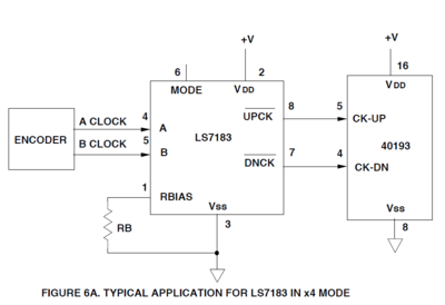
Rotary encoders create quadrature signals on two channels (A and B) corresponding to the speed and direction of a motor. Some encoders produce up to a million counts per revolution. For very fast quadrature signals there is no way that a software quadrature decoder can avoid overrun errors. Instead we may use the LS7183 chip to translate the A and B quadrature signals into brief pulses indicating up-count or down-count. The up and down counts can be configured as external input signals to increment counters on the PIC32. By reading the counters on the PIC, we can determine the angle of the motor.
Details
The resistor bias is used to control the pulse width of the up and down counts. The mode (1X, 2X, 4X) is used to multiply the quadrature clock rate by 1, 2 or 4. The mode is selected by connecting MODE to
- VSS (GND) -> 1X
- VDD (3.3V) -> 2X
- Float (don't connect to anything) -> 4X
The UP and DOWN count pins should be connected to external counters on the PIC32.
Sample Code
The full code can be downloaded here. The code configures 2 external counters (see Counters and Timers) that will increment with each pulse received from the LS7183. The example sends the encoder position via RS232 to your PC.
The main piece of code shown below reads the UP and DOWN counters. With a variable called bigcount, it adds the the recent UP counts, subtracts the down counts and adjusts for roll-over of the counters. The full code placed this code in the main while loop, but this code can be placed in an ISR if you want to read the encoder at a given rate.
count0 = ReadTimer4();  // in your routine this must be done at least every 32000
	                // encoder counts to avoid rollover ambiguity
count1 = ReadTimer5();

bigcount += count0 - last0; // add on the recent up-counts, since the last time

if (count0 < last0){
  bigcount += 65536; 		// count0 only increments, so if it got lower
  		                //it must have rolled over
}

last0 = count0;

bigcount -= count1 - last1; // we're not worrying about rollover of the 32 bit bigcount total

if (count1 < last1){
  bigcount -= 65536;
}

last1 = count1;
