NU32: Quickstart
THIS PAGE REFERS TO A PRE-RELEASE VERSION OF THE NU32 PIC32 DEVELOPMENT BOARD. FOR INFORMATION, SAMPLE CODE, AND VIDEOS RELATED TO THE PRODUCTION VERSION (2016 AND LATER), AND TO THE CORRESPONDING BOOK "EMBEDDED COMPUTING AND MECHATRONICS WITH THE PIC32 MICROCONTROLLER," VISIT THE NU32 PAGE.
This is a quick-start guide to programming the NU32, using the bootloader and the PICkit3.
Follow this guide to test your NU32 with the bootloader application, and test your installation of MPLAB X.
If you are looking for more details about programming the PIC32, take a look at NU32: Starting a New Project and Putting it on the NU32 and NU32: A Detailed Look at Programming the PIC32 on the NU32
Before you start
You need:
- A computer with a USB port (any operating system is fine)
- An NU32 board, 6 V power supply for it, and a USB cable to attach to your computer
- Software
- Download and install the Microchip XC32 compiler (or search for microchip xc32 compiler if this link breaks). Note: it is also known as the XC32++ compiler.
- Download and install the Microchip MPLAB X IDE (or search for MPLAB X IDE if this link breaks)
- Download and install the FTDI Virtual Com Port (VCP) driver for your OS
- Download the NU32 bootloader communication utility
- Download and unzip the PIC32 quickstart code, which contains NU32test.hex, simplePIC.c, NU32bootloaded.ld, simplePIC_standalone.c, talkingPIC.c, NU32.c, and NU32.h
- Recommended: reference reading material from Microchip (these are local archived versions)
- The PIC32MX5XX/6XX/7XX Family Data Sheet (5 MB pdf)
- The PIC32 Reference Manual (12 MB pdf)
You can now proceed through the Chapter 1 Quickstart document or the wiki page below.
Test the bootloader, 1.2.1
Begin by testing your NU32. Plug the mini USB cable into the board and your computer. Plug the 6V wall power into the board. Turn on the NU32 power switch, and a red LED should turn on. Press and hold the reset button, press and hold the user button, release the reset button, and release the user button. LED2 should blink. If it does not, the bootloader firmware has not been installed on your board. Also check to see what the FTDI driver has named the NU32 ports. The NU32 board will create 2 virtual serial ports on your computer. In Windows, the ports will be named something like COM10 and COM11, or some two consecutive numbers. On a Mac or in Linux, the ports will named DEV/TTY/##A and ##B. (You can ignore the CU versions). If you cannot verify your ports, re-install the FTDI drivers.
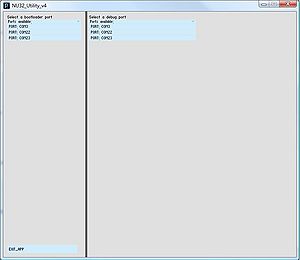
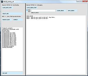
Now use the NU32 Utility to load NU32test.hex on your board. This will test the communication link between your computer and the NU32. Open NU32_Utility:
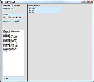
The left hand side of the Utility is used for loading code onto the NU32. Select the larger of the two ports (so COM11 instead of COM10, or ##B instead of ##A) to allow communication between your computer and the bootlodaer on the NU32. Click "Select HEX" and navigate to NU32test.hex. The NU32 must be in bootloading mode to accept code - this is when LED2 is blinking. Put the NU32 in this mode by pressing and holding reset, pressing and holding user, releasing rest, then releasing user. Or, depending on the code already on the NU32, clicking "Request Boot".
The text box should report: "Trying to connect... Connected to bootloader v4.0!"
Now click Program. When the message "Programming Complete!" appears, click "Run", and the program will execute.
Using NU32test.hex, if you press the user button, LEDs 2 and 3 will blink out of phase, and stop blinking when you don't push User.
Test MPLAB X, 1.3.1
Now create an MPLAB X project to test your installation of MPLAB X. First, create a project. Second, download the sample code and add it to the project. Third, compile the code, and use the NU32 Utility to load the .hex file.
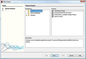
Open MPLAB X and go to "File -> New Project..."
Keep "Microchip Embedded" and "Standalone Project" highlighted and click "Next >"
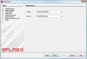
Select "32-bit MCUs (PIC32)" from "Family:" and "PIC32MX795F512L" from "Device:" and click "Next >"
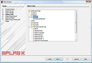
If you are using the bootloader to load code, it doesn't matter which tool you select, but if you are using the PICkit3 programmer, select "PICkit3", and click "Next >"
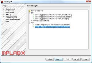
Select the compiler you will use, "XC32 (v1.xx) ..." and click "Next >"
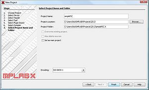
Give your project a name, like "SimplePIC", and click "Finish"
MPLAB X will make a new folder called "SimplePIC.X" at the location where you saved your project. This folder is where all of your files should be located.
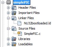
Download SimplePIC.c and NU32bootloaded.ld, and place them in the "SimplePIC.X" folder. In MPLAB X, in the file tree on the left, right-click on the "Source Files" folder under the "SimplePIC" project. Select "Add Existing Item..." and select "SimplePIC.c". Right-click on the "Linker Files" folder and select "Add Existing Item..." and select "NU32bootloaded.ld".
This code is already complete, so build it by clicking the Hammer icon, "Build Main Project". Note that if there are several projects in the project tree on the left, the one that is highlighted will be built, so be sure to right-click on the project you are making and select "Set as Main Project". Also note that you code will compile, but not run, if you forget to add "NU32bootloaded.ld" to your project, from the project folder. "NU32bootloaded.ld" needs to be copied into every project folder you make, and added to the "Linker Files" folder in MPLAB X. Use the Hammer and Broom icon, "Clean and Build Main Project", to rebuild your code if you add a new linker file, otherwise MPLAB X won't necessarily know that you added a new linker file.
When your code has compile, you should get a message "Compile Successful". This process has created a .hex file "(project).X.production.hex " in your project folder at "(project.x)\dist\default\production". Use this .hex file and the NU32 Utility to load the code onto your NU32.
Run the code and the LEDs blink all the time, and stop when you hold the user button.
Projects with the standard NU32 functions, 1.4.1
The NU32 board has dedicated several pins on the PIC32MX795F512L to special funtions - A4 and A5 are LEDs, C13 is the user button, G6, G7, G8 and G9 are used for programming the NU32 over UART3, and F2, F8, D14 and D15 are for general communication with the computer over UART1. These pins should not be used for any other function because they are hardwired to other chips on the NU32, unless you are very careful.
These pins can be set up to their dedicated functions by including NU32.c and NU32.h in your project.
Use talkingPIC.c, NU32.c, NU32.h, and NU32bootloaded.ld to build a project that will communicate with the computer.
You can open the smaller of the two NU32 ports in the NU32 Utility, or use CootTerm. In CoolTerm, use a baud of 230400, and check the "CTS" and "DTR" boxes.
Using the PICkit3, 1.2.2
If you don't want to use the bootloader and the Utility, and have a PICkit3 programmer, you can program the NU32 directly from MPLAB X. In this case, you do not need to include a linker file, but you do need to set the Configuration bits normally set by the bootloader.
Build a project with talkingPIC.c, NU32.c, and NU32.h. At the top of "NU32.h", add "#define NU32STANDALONE" to line 3. This will include the Configuration bits to make the PIC run the same as code would when using the bootloader.
Plug the PICkit3 into the NU32, lining up the white triangles. Press the "Make and Program Device" button in MPLAB X (green downwards arrow) to program the NU32.
