Flip-Flops and Latches
Flip-flops are a useful type of digital device that can store binary states, or be used as a sort of digital toggle switch. Flip-flops can be built up from distinct logic gates, but they can easily be bought in packaged chips. The flip-flop is a digital device, so its output (labeled with a Q in schematic diagrams) will take on the value of either 1 (high) or 0 (low). Many flip-flops will also provide the complementary output (an inverted output).
Edge Triggering
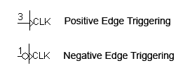
Because the state of a flip-flop often depends on the previous state of a circuit (for example, the output of one flip flop may be the input to another), and because each flip-flop and logic gate needs a certain amount of time to switch its output, we usually clock the devices, that is, we synchonize all the flip-flops to change states at the same time with a clocked pulse. Flip-flops are edge triggered; they either change states when the clock goes from 0 to 1 (positive/rising edge) or when the clock goes from 1 to 0 (negative/falling edge).
The symbols used for positive and negative edge triggering on flip-flops:
Asynchonous Inputs
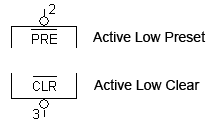
Many flip-flops will also have a clear (CLR) and preset (PRE) terminal. These inputs are typically inverted, so they are active when the input signal is low (Digital#Active_Low_Input Active Low Input). The CLR and PRE signals can be asserted any time and don't have to be edge triggered; they will override any other inputs, including the clock.
The symbols used for clear and preset (the bubble indicates an inverted signal):
| PRE | CLR | Output |
|---|---|---|
| 0 | 0 | Error state |
| 0 | 1 | 1 |
| 1 | 0 | 0 |
| 1 | 1 | Depends on inputs and clock |
Types of flip-flops
There are several types of flip-flops but the two most important kind are the D and J-K flip-flops.
D flip-flop
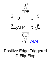
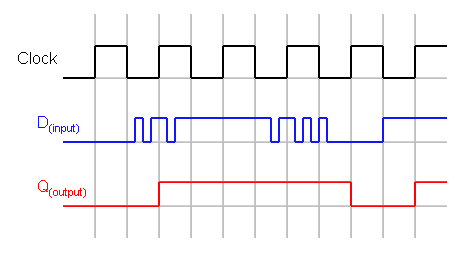
The D (Data) flip-flop has an input D, and the output Q will take on the value of D at every triggering edge of the clock pulse and hold it until the next triggering pulse. The D flip-flop is usually positive edge triggered.
The truth table for a positive edge triggered D flip-flop:
| D | CK | Q |
|---|---|---|
| 0 | ↑ | 0 |
| 1 | ↑ | 1 |
| X | 0,1 | Q0 |
(↑ indicates a rising edge on the clock pulse; X indicates that it has no effect on outcome)
Timing diagram for the positive edge triggered D flip-flop:
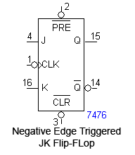
JK flip-flop
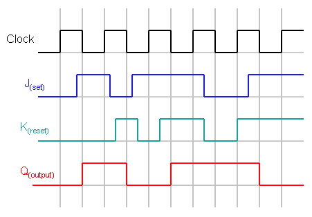
The JK flip-flop has two inputs, labeled J and K. J corresponds to a "set" signal, and K corresponds to a "reset" signal.
At the triggering edge:
If J is 1 and K is 0, Q is 1.
If J is 0 and K is 1, Q is 0.
If J and K are both 0, the output stays the same as it was before.
If J and K are both 1, the output is inverted.
The JK flip-flop is usually negative edge triggered.
The truth table for a negatively triggered JK flip-flop:
| J | K | CK | Q |
|---|---|---|---|
| 0 | 0 | ↓ | Q0 |
| 0 | 1 | ↓ | 0 |
| 1 | 0 | ↓ | 1 |
| 1 | 1 | ↓ | Q'0 |
| X | X | 0,1 | Q0 |
The timing diagram for the negatively triggered JK flip-flop:
Latches
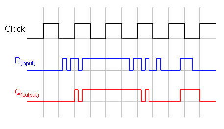
Latches are similar to flip-flops, but instead of being edge triggered, they are level triggered.
The most common type of latch is the D latch. While CK is high, Q will take whatever value D is at. When CK is low, Q will latch onto the last value it had before CK went low, and hold it until CK goes high again.
Timing diagram for the D latch:
