Adding a magnetic encoder to a GM3 Gearmotor
You may want to add a rotation encoder to your wheel motor. Optical encoders are popular because of the very high resolution (counts per rev) you can obtain.
Here we will add a magnetic encoder, which has advantages of low cost and dirt insensitivity. The resolution is only 1 count per revolution of the motor, but because of the gearing (transmission ratio) it is many counts per revolution of the wheel.
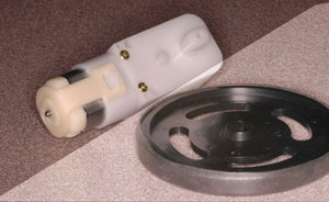
Shown here is the Hobby Engineering Gearmotor-3 with traction wheel, which has a 224:1 transmission ratio
You can also add a magnetic encoder to the Gearmotor-9, which has a 143:1 transmission ratio
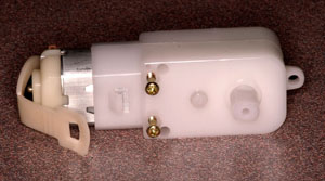
Unclip the motor retention band using pliers
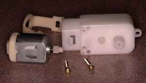
Remove the motor by hand, and the two screws with a small philips screwdriver.
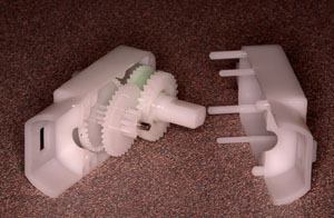
Pry the case apart with a thin blade
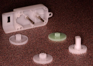
Pull all four gears out
Use 92% alcohol to wipe the grease off the crown gear, the one that turns fastest.
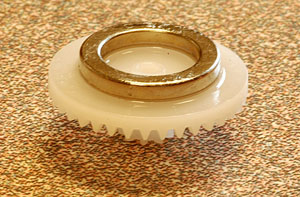
Use superglue to adhere a ring magnet to the back (flat) surface. I found it best to place the magnet, add drops of glue on the outside perimeter, and wick away excess glue with the edge of a paper tissue.
Let it cure. If you are impatient, Blick Art Materials carries Zip Kicker superglue accelerator (and several kinds of superglue.)
This magnet is magnetized such that one semicircle is north and the other south (magnetized left-to-right in the photo)
We have lots of these; they are from Amazing Magnets
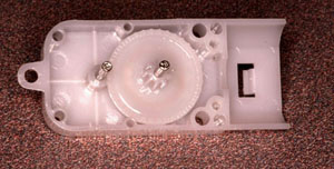
Put it back together. In this photo you can see the magnet ring faintly through the gear
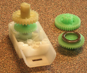
This is the Gearmotor-9, which has slightly different construction than the Gearmotor-3. You only have to take it apart this far.
Unfortunately it has ribs molded into the case where the ring magnet will go. The first gear, when carrying the magnet, still seems to clear the ribs OK, but just barely. One could mill or dremel the ribs down, to be sure
Clean the back surface and superglue a HAL506 hall switch (or similar) to it.
You can find the point of strongest magnetic field on the surface by using a tiny bit of a staple or other steel wire -- it will slide over the surface to the point of strongest field strength.
You can take advantage of this probe to trace out the ring magnet on the surface, as you turn the motor. Find a convenient place to mount the Hall switch.
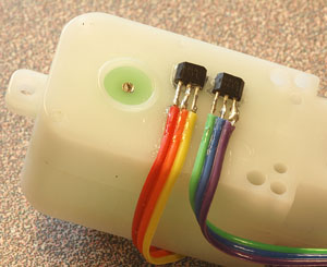
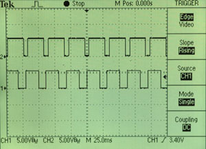
A better way, especially if you want to mount two hall switches in quadrature as I have done here on the Gearmotor-9, is to wire them first and then look at their traces on a scope as the motor is operating. Find the best place to mount them and then glue them in place.
The order of the pins in this photo is 1-2-3:
pin 1(red, green) = +5V pin 2 (orange, blue) = ground pin 3 (yellow, purple) = open collector output
Ideally the scope trace will show two square waves, each with 50% duty cycle, and 90 degrees out of phase. I didn't do such a good job here because I guessed the position of the hall sensors. It will work nevertheless.
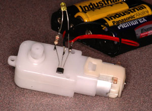
You may find that if you operate the motor from the same supply as the hall sensors, the motor generates so much electrical noise that the hall sensors will operate erratically. You can solve this with a 0.1uF capacitor across the power supply leads of the hall switch.
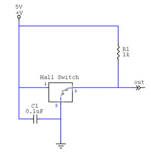
Using a hall switch.
The HAL506 and most hall switches have what is called an open-collector output. That means they can ground their output (for logic 0) but they do not source their output (for logic 1). It is as if there were a switch inside which closes, grounding the output, when a magnetic field is detected. It is the user's responsibility to use a pull-up resistor (R1) to assure that the output voltage is +5 when the switch is open.
Also shown here is the power supply shunt capacitor C1 that will assure reliable operation even if there is noise on the power supply lines.
