PCB Artist
Advanced Circuits and PCB Artist
Advanced Circuits (www.4pcb.com) is a company based in Colorado known for their quick turn around and good prices on low volume printed circuit board (PCB) orders. This has been the main supplier for PCBs created by students for class or research at Northwestern.
Previously, the PCB was created in TraxxMaker or other CAD PCB program, many of which are outdated and difficult to use. Advanced Circuits has created PCB Artist, free software to create schematics and PCBs. This software is designed to order only from Advanced Circuits, although the file type produced is .brd. This somewhat simplistic software is very intuitive (once comfortable) and allows for simple changes and editing. Additionally, the component library offered is up to date and contains many specific components. This Wiki page will cover the development and ordering process of the a simple PCB board.
Contact at Advanced Circuits
Jackie Sartin - Regional Sales Manager
E-mail: jackies@4pcb.com Call: 1-800-979-4PCB (4722) Ext: 1685
Getting Setup
- Have a complete circuit schematic and know exactly what parts (including part numbers) you are using.
- Download the software Or, type “PCB Artist” into google. Then click the download button in the middle of the screen.
Ordering
Ordering Options:
- Barebones: These boards are very basic. They do not have solder mask (the green coating), or text on the board and the traces are exposed. However, they are fairly cheap (charged by area) and they ship in 1 business day. Perfect for prototyping. More info
- 33- Each 2 layer PCBs can be ordered for $33 each, shipping in about a week. These are complete, boards with screen printing and solder mask. The max size is 60 square inches. With the promo “student” the min qty of 4 is waived, allowing you to order a single board. More info
- Other promotions: Advanced Circuits offers various other promotions for students and first time customers. If you have questions, contact Jackie Sartin, our rep. More info
After ordering, it’s a good idea to call and make sure they have received your order, check the turn around date, promotions and any other info.
Advantages
Many robots are limited by the use of motorized wheels. However, there are many advantages for building a robot that mimics the motion of a snake. Several advantages for movement of a snake robot are listed below:
- Move across uneven terrain, since it is not dependent on wheels
- Possibly swim if water-proofed
- Move across soft ground such as sand, since it can distribute its weight across a wider area
Also, from a systems standpoint, the snake robot can be very modular with many redundant segments. As a result, it is very easy to replace broken segments as well as shorten or lengthen the robot.
Disadvantages
Although there are many advantages for building a snake like robot, there are several disadvantages which are listed below:
- Low power and movement efficiency
- High cost of actuators (servos or motors)
- Difficult to control high number of degrees of freedom
(Ma, 206)
Robot Snake Motion
Real snake motion does not follow specified equations. However, research has proven that the serpentine motion of a snake can be modeled with the following equations (Saito etal, 72-73):
where the parameters a, b, and c determine the shape of the serpentine motion. The graph shows how the parameters influence the serpentine curve. Basically, a changes the appearance of the curve, b changes the number of phases, and c changes the direction.
The serpentine curve can be modeled with a snake like robot by changing the relative angles between the snake robot segments using the following formula with the number of segments (n):
where α , β , and γ are parameters used to characterize the serpentine curve and are dependent on a, b, and c as shown below:
The equations above for φi,α,β, and γ were used in this snake like robot as shown in the code section.
Mechanical Design
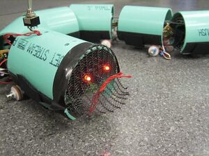
The robotic snake consists of a head segment and several body segments. The head segment houses the onboard microcontroller and xBee radio. The body segments house the servo motors and the batteries required to power each motor. As the snake is designed to be modular, there is no limit to the number of body segments. More segments will allow it to move more smoothly, while fewer segments will be easier to control. For this design, seven body segments were used due to material limitations.
Mechanically, the snake is designed to move in a serpentine motion, imitating the motion of a real snake. As discussed above, real snakes move with anisotropic coefficients of friction. It is difficult to locate materials with this property, but passive wheels satisfy the friction requirements. The friction will be lower in the direction of rolling, thus providing the required difference in friction. The only problem with this approach is that the wheel may slide in the normal direction if the weight applied to the wheel is not sufficient.
Parts List
- Motors: Futaba S3004 standard ball bearing RC servo motor, Tower Hobbies LXZV41 $12.99
- Wheels: McMasterCarr Acetal Pulley for Fibrous Rope for 1/4" Rope Diameter, 3/4" OD McMasterCarr 8901T11 $1.66
- O-Rings (Tires): McMasterCarr Silicone O-Ring AS568A Dash Number 207, Packs of 50 McMasterCarr 9396K209 $7.60/50
- PVC Pipe: McMasterCarr Sewer & Drain Thin-Wall PVC Pipe Non-Perforated, 3" X 4-1/2' L, Light Green McMasterCarr 2426K24 $7.06
- 1/8th inch plastic for chassis: (Shop Stock) or McMasterCarr Polycarbonate Sheet 1/8" Thick, 12" X 12", Clear, McMasterCarr, 8574K26 $6.32
- Dowel Pins: 1" long, 1/4" diameter
- Sheet Metal: For the connecting segments
- Fasteners: Screws for the servos and chassis, washers for the standoffs
- Standoffs: Used 1" and 1/2" to achieve a level snake
- Velcro: To attach battery packs and housing to the chasis
- Ball caster: For the head
The Body Segments
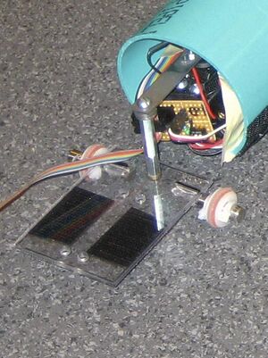
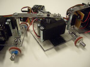
Each of the body segments are identical and includes a chassis, a servo, a connector, standoffs and two passive wheels as can be seen in the picture.
Video of 3 body segments moving
Chassis
The base of the chassis is made from a thin (approx. 1/8th inch) piece of polycarbonate. The chassis must be wide enough to hold a servo motor with a AAA battery pack on each side and long enough for the servo and a standoff (the connection for the previous segment). The polycarbonate was cut into a rectangle to meet the specifications for our servo motor. Five holes were then drilled in the rectangle, four to mount the servo and one for the standoff. The holes are drilled to allow the servo to be located in the center of the chassis.
Connector
A connector was machined to attach to the servo horn of one body segment and to attach to the next segment's standoff. The length of this connector is about 3 inches and is just long enough to prevent collision between segments. A shorter beam allows for greater torque. This connection needs to be as tight as possible and the beam must be mounted perpendicular to the chassis.
Standoffs
Standoffs were used to attach the servo to the chassis and to attach the connector to the chassis. Two standoffs (1 in and 1/2 in) and several washers were used to make the connector parallel to the ground.
Passive Wheels
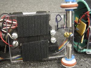
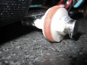
Passive wheels were mounted to the bottom of the chassis. Each wheel was made of a 3/4 inch pulley and an o-ring. The o-ring was used to increase friction with the ground. The wheels have been set on polished metal dowel pins which allow the wheels to rotate more freely than when placed on wooden dowels. The dowel pin axles were mounted (hot glue works but is not very strong) in the center of the segment. The center of the segment is not the center of the polycarbonate rectangle. Instead, the entire segment length is the distance from the standoff on one chassis to the center of the servo horn on the other. In this project, the length of the connector was made to be about half the length of the segment. Therefore, the wheels were placed at the same location as the stand off as can be seen in the image. The wheels are held in place with zip ties.
Fully Assembled Body Segment
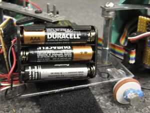
A fully assembled chassis has a mounted servo and is connected to a segment on either side. AAA batteries packs were attached to the sides of the motor with velcro to allow easy removal. The small electronic circuit board for each segment was mounted on the front of the motor to allow easy access to the switch. (See Electronic Design for more information on the circuit board and batteries)
