Granular Flow Rotating Sphere
Team Members
- Brian Kephart - Electrical Engineering Class of 2009
- Jonathan Shih - Mechanical Engineering Class of 2009
- Kristi Bond - Mechanical Engineering Class of 2008
Overview
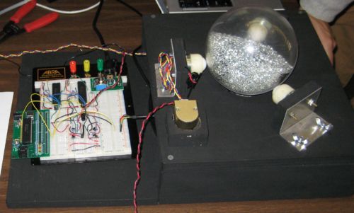
A clear sphere is filled with grains of different sizes. Our apparatus rotates this ball about two different axis based on a series of user inputs. The user inputs the specific values for things such as angle and rotational speed into Matlab. Our device takes these inputs and processes them using a series of master and slave PICs to appropriately control the motors. The motors then turn for the input duration at the desired speed causing the ball to spin correctly due to the frictional connection between both motors and the sphere or lazy susan, respectively.
This apparatus will be used for the study of granular flow and the mixing of particles within the sphere. It was important to leave the ball as visible as possible to allow for pictures to be taken of the grains within from many angles. With this apparatus we hope to aide the study of granular flow theory and allow the researches to use the device for many different applications.
Mechanical Set-up
Main Housing
The main housing, or case, for our design is composed of the following pieces.
- One 13.5” x 12” x ¾” plywood rectangle
- One 13.5” x 12” x ¾” plywood rectangle with a 3.5” diameter circle removed from the center
- Two 12” x 2.5”x ¾” plywood rectangles
The two larger rectangles form the top and bottom of the set-up with the two smaller rectangles placed vertically between to form a box with two open ends on the front and back face.
Ball Support
Three ball casters are placed on vertical mounts around the center circle of the top piece of the housing at equal angles. These casters prevent the ball from moving in any horizontal direction so it is only free to rotate. One of these casters is adjustable to allow the user to make sure the ball is correctly supported above the drive wheel. The force of gravity is strong enough to prevent the ball from moving up and out of the housing and also ensures a good connection with the drive wheel that is placed directly under the center of the sphere.
Main Drive Wheel
The main drive wheel is centered under the rotating sphere. The wheel is mounted onto a ¼” aluminum shaft which is connected to the Pittman motor with a flexible coupling and is also supported by a sleeve bearing on the other side of the wheel.
Lazy Susan
The main drive wheel with its corresponding motor and other components are all mounted on top of a lazy susan that is centered on the bottom piece of the housing and secured with screws. This lazy susan allows rotational motion but prevents movement in any other direction allowing the wheel to turn but always have the same center of contact with the sphere above. It is important to ensure that the drive wheel has a good connection with the sphere above because the frictional force between the wheel and the sphere must be as large as possible so that as the wheel spins the ball spins at the same rate.
Position Control Motor
A second motor is used in our design to turn the lazy susan. The motor is mounted vertically through the top plate. Another, smaller, drive wheel is mounted directly to the motor shaft and then aligned with only the top, free half of the lazy susan. A second, idler wheel is mounted on the bottom plate, so the drive wheel is sandwiched between this wheel and the lazy susan. This ensures that the drive wheel is always in contact with the lazy susan because the idler wheel exerts only a normal force. Again, this is to ensure there is no slip between the lazy susan and the drive wheel so it is automatically controlled more easily.
Complete Parts List
| Part | Part No. | Qty |
|---|---|---|
| Pittman GM8224 motor | --- | 2 |
| Helical Beam Set-Screw Shaft Coupling | 9861T508 | 1 |
| Mounted Sleeve Bearing | 5912K21 | 1 |
| Flange Mount Ball Caster | 5674K77 | 3 |
| Lazy Susan | 1443T2 | 1 |
| Drive Wheel | 60885K23 | 1 |
| Small Drive Wheel | 2471K12 | 1 |
| Idler Wheel | 60885K79 | 1 |
| 1/4” Aluminum Rod | --- | --- |
| Aluminum Sheet Metal | --- | --- |
| Plywood | --- | --- |
Circuitry
Summary
Our project was unique in that we relied on the use of three different PICs to precisely coordinate the motion of our ball. The main reason for this was because the 18F4520 chip only has enough encoder inputs for one Pittman motor.
Component List
| Part | Part No. | Qty |
|---|---|---|
| PIC18F4520 Prototyping Board | --- | 1 |
| Microchip 8-bit PIC Microcontroller | PIC18F4520 | 3 |
| Pittman Motor with Encoder | GM8224 | 3 |
| Hex Inverter Chip | SN74HC04 | 1 |
| Counter Chip | LS7083 | 2 |
| H-Bridge Chip | L293 | 1 |
| Diodes | 1N4001 | 8 |
| 10K Resistor | --- | 2 |
| Hall Effect Sensor | A3240LUA-T | 1 |
| Big Cat Super Strong Magnet | PM20134 | 1 |
Set Up
The electrical design for our project was pretty basic. All of our components (including the Pittman motors) were powered with 5V DC.
PICs
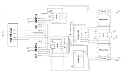
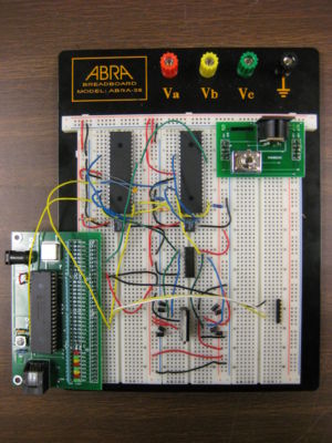
The three PICs communicated via I2C, which enabled us to control the two motors by telling the master PIC what to do (more information can be found here). We designated the PIC on the 18F4520 Prototyping Board as the "Master" and the other two PICs as the "Slaves." It is important to connect the clock from the prototyping board to the two Slave PICs, but the two main lines of communication are shared on pin 18 (RC3) on each chip, and pin 23 (RC4).
H-Bridge
Each slave PIC sends an individual pulse to one of the two H-bridges (the L298 has two). The pulse width determines the direction and speed of each motor. At 50% duty cycle, the motor is at rest, while at 0 and 100% duty cycles the motor runs at maximum speed but in opposite directions. Pin 16 from the first slave PIC needs to connect to pin 10 on the L298, while other other should connect to pin 5.
Hex Inverter
Now pins 5 and 10 from the H-bridge needs to go into pins 1 and 13 on the hex inverter chip. The outputs of these two need to go back the the H-bridge as an inverted signal for pulse width modulation (pin 1 to L298's pin 12, and pin 14 to L298's pin 7).
Counter
The last main component that needs to be implemented in the counter chip. This enables us to take fewer counts from the high encoder on the Pittman motors to control the movement of the motor. Pins 4 and 5 are used to connect directly to the blue and yellow lines on each Pittman encoder. Pins 1, 3, and 6 should all be hooked to ground, while pin 2 should be +5V. Pins 7 and 8 should connect to pins 15 and 6, respectively on the slave PIC that is correspondent to this counter chip.
Schematic
Here is a visual representation of how our circuit components fit together:
Programming
Code Overview
PIC Code
BKSBallMasterv1.c
BKSBallSlavev1.c
MATLAB Code
The GUIDE toolset in MATLAB was used to create the GUI.
BKSBallControl.m
BKSBallControl.fig
Results
Das.


