Robot Snake
Overview
Team Members
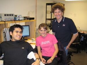
- Michael Hwang - Electrical Engineer - Class 2008
- Andrew Long - Mechanical Engineer - Class 2009
- Clara Smart - Electrical Engineer - Class 2009
Snake Motion
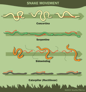
Snakes are able to adapt their movement to various environments. For instance, snakes can move across extreme environments such as sand, mud and water. Research has discovered there are four types of snake motion, as shown in the image. These motions include; serpentine movement, rectilinear movement, concertina movement and side-winding movement.<ref>Ma, Shugen. "Analysis of creeping locomotion of a snake-like robot." Advanced Robotics Vol.15, No.2 (2001): 205</ref> The most common motion exhibited by most snakes is serpentine motion where section follows a similar path. In order for snakes to successfully locomote using serpentine motion, the belly of the snake must have anisotropic coefficient of friction for the normal and tangential directions. Specifically, the normal friction must be greater than the tangential friction. As a result, when the snake exhibits a force on the ground, it will move in the tangential direction without slipping in the normal direction.<ref>Saito, Fukaya, Iwasaki. "Serpentine Locomotion with Robotic Snakes". IEEE Control Systems Magazine (Feb 2002): 66.<ref/>
Advantages / Disadvantages of Robotic Snake Motion
Advantages
Many robots are limited by the use of motorized wheels. However, there are many advantages for building a robot that mimics the motion of a snake. Several advantages for movement of snake robot are listed below:
- Move across uneven terrain since it is not dependent on wheels
- Possibly swim if water-proofed
- Move across soft ground such as sand since it can distribute its weight across wider area
Also, from a systems standpoint, the snake robot can be very modular with many redundant segments. As a result, it is very easy to replace broken segments as well as shorten or lengthen the robot.
Disadvantages
Although there are many advantages for building a snake like robot, there are several disadvantages which are listed below:
- Low power and movement efficiency
- High cost of actuators (servos or motors)
- Difficult to control high number of degrees of freedom
Cite = Page 206
Robot Snake Motion
Real snake motion does not follow specified equations. However, research has proven that the serpentine motion of a snake can be modeled with the following equations:
where the parameters a, b, and c determine the shape of the serpentine motion. The graph shows how the parameters influence the serpentine curve. Basically, a changes the appearance of the curve, b changes the number of phases, and c changes the direction.
The serpentine curve can be modeled with a snake like robot by changing the relative angles between the snake robot segments using the following formula with the number of segments (n):
where α , β , and γ are parameters used to characterize the serpentine curve and are dependent on a, b, and c as shown below:
The equations above for φi,α,β, and γ were used in this snake like robot as shown in the code section.
Mechanical Design
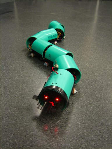
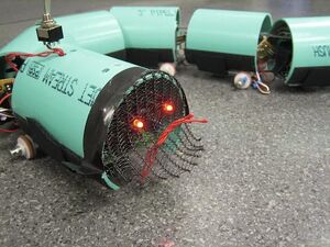
The robotic snake consists of a head segment and several body segments. The head segment houses the onboard microcontroller and xBee radio. The body segments house the servo motors and the batteries required to power each motor. As the snake is designed to be modular, there is no limit to the number of body segments. More segments will allow it to move more smoothly, while fewer segments will be easier to control. For this design, seven body segments were used due to material limitations.
Mechanically, the snake is designed to move in a serpentine motion, imitating the motion of a real snake. As discussed above, real snakes move with anisotropic coefficients of friction. It is difficult to locate materials with this property, but passive wheels satisfy the friction requirements. The friction will be lower in the direction of rolling, thus providing the required difference in friction. The only problem with this approach is that the wheel may slide in the normal direction if the weight applied to the wheel is not sufficient.
The Body Segments
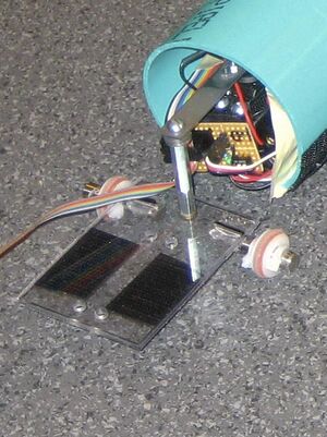
Each of the body segments are identical and includes a chassis, a servo, a connector, standoffs and two passive wheels as can be seen in the picture.
Chassis
The base of the chassis is made from a thin (approx. 1/8th inch) piece of polycarbonate. The chassis must be wide enough to hold a servo motor with a AAA battery pack on each side and long enough for the servo and a standoff (the connection for the previous segment). The polycarbonate was cut into a rectangle to meet the specifications for our servo motor. Five holes were then drilled in the rectangle, four to mount the servo and one for the standoff. The holes are drilled to allow the servo to be located in the center of the chassis.
Connector
A connector was machined to attach to the servo horn of one body segment and to attach to the next segment's standoff. The length of this connector is about 3 inches and is just long enough to prevent collision between segments. A shorter beam allows for greater torque. This connection needs to be as tight as possible and the beam must be mounted perpendicular to the chassis.
Standoffs
Standoffs were used to attach the servo to the chassis and to attach the connector to the chassis. Two standoffs (1 in and 1/2 in) and several washers were used to make the connector parallel to the ground.
Passive Wheels
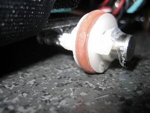
Passive wheels were mounted to the bottom of the chassis. Each wheel was made of a 3/4 inch pulley and an o-ring. The o-ring was used to increase friction with the ground. The wheels have been set on polished metal dowel pins which allow the wheels to rotate more freely than when placed on wooden dowels. The dowel pin axles were mounted (hot glue works but is not very strong) in the center of the segment. The center of the segment is not the center of the polycarbonate rectangle. Instead, the entire segment length is the distance from the standoff on one chassis to the center of the servo horn on the other. In this project, the length of the connector was made to be about half the length of the segment. Therefore, the wheels were placed at the same location as the stand off as can be seen in the image. The wheels are held in place with zip ties.
Fully Assembled Body Segment
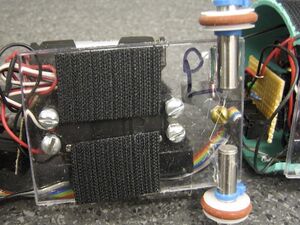
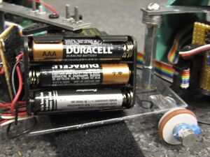
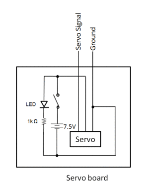
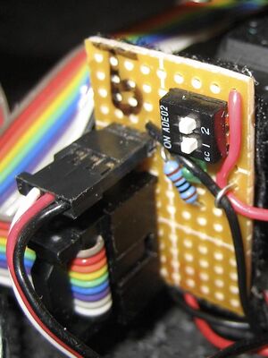
A fully assembled chassis has a mounted servo and is connected to a segment on either side. AAA batteries packs were attached to the sides of the motor with velcro to allow easy removal. The small electronic circuit board for each segment was mounted on the front of the motor to allow easy access to the switch. (See Electronic Design for more information on the circuit board and batteries.
The Head Segment
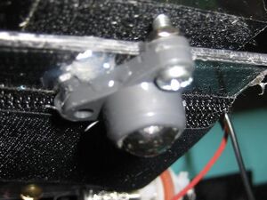
The head segment is similar to the body segments except that it contains a PCB board with a PIC instead of a servo motor. The head segment is the same width but slightly longer than the body segment. A ball caster was added to the front of the segment to help support the extra length and help the wheels stay on the ground.
Protection and Visual Appeal
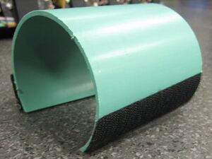
As a final step, housing for each segment was created from 3" PVC pipe. The pipe was cut into segments the same length as the chassis. The bottom of the pipe was cut off, allowing it to sit flat on the chassis. The housing provides a protective covering for the servo, batteries and electronics. The pipe was attached with velcro straps which mounted under the chassis. This housing can be easily removed to debug and to change batteries.
Mechanical Debugging
Wheels come off the ground: Add washers to the standoffs to force the chassis to be parallel to the ground.
Wheels slide, but do not roll: Increase frictionby either adding weight to the segment or changing the "tires" (the o-ring).
The segments slip when the servo rotates: Tighten the screws for the connector standoffs, both above the beam and below the chassis.
Electronics
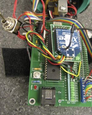
The each segment of the snake contains a Futaba Standard RC Servo. Each servo has 3 wires: power, ground, and signal.
Needs description of servo - include discussion of how we aligned them (through code)
Needs discussion on batteries. Rechargeable vs Alkaline, 4 vs 5 etc.
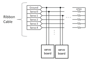
Needs circuit diagram for servo boards and/or picture
Needs description of ribbon cable? (ie be careful with it)
Needs reason for terminator
PIC Code
Servo Control
The main function of the PIC microcontroller was to control multiple servos (seven in our case). Timer1is set to overflow every 20 milliseconds and trigger an interrupt. When the interrupt is triggered, Timer1'scounter is set to the value held by TMR1_20MS, which will cause the interrupt to trigger again 20 ms later. At the beginning of the interrupt, all the pins connected to the servos are set high. While Timer1 is less than the value held by TMR1_2point25MS, Timer1 is polled, and the value is compared sequentially to the values in the RCservo array. If the value of Timer1 is greater than a value in RCservo, the the corresponding pin is set low. After all the values have been compared, Timer1 is polled again and the process repeats until 2.25 ms have elapsed (when Timer1 > TMR1_2point25MS). After all the servos signals have been sent, the values in the RCServo array are updated to prepare it for the next 20ms interrupt.
Although this method of timing the pulse trains has a lower resolution than using interrupts (see RCservoSoft.c), it allows one to add and remove servos more easily and not have to decrease the frequency of the servo signal pulse train. With a 40MHz clock and seven servos, the resolution was about 8us, which was good enough for this purpose.
Serial Communication
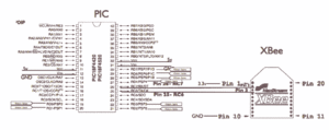
The PIC communicates serially with a XBee radio. When a byte is received in the UART receive buffer, a high-priority interrupt is triggered. The received byte is put into a switch-case statement, and the corresponding parameters are updated.
SnakeServos.c
/*
Andy Long, Clara Smart, and Michael Hwang's snake robot code.
*/


#include <18f4520.h>
#device high_ints=TRUE        // this allows raised priority interrupts, which we need
#fuses HS,NOLVP,NOWDT,NOPROTECT
#use delay(clock=40000000)
#use rs232(baud=9600, UART1)

#include <main.h>
#include <math.h>

/*
Put your desired high duration here;
3200 is center
1000 is 90 deg right
5400 is 90 deg left
*/
int16 RCservo[7];

volatile float a = A_DEFAULT;
volatile float b = B_DEFAULT;
volatile float c = C_DEFAULT;

volatile float alpha;
volatile float gamma;
volatile float beta;
volatile float speed = 0;
volatile float prev_speed = SPEED_DEFAULT;
float t = 0;

#INT_TIMER1 // designates that this is the routine to call when timer1 overflows
//generates servo signals
void ISR_20MS(){
   volatile unsigned int16 time;
   set_timer1(TMR1_20MS);
   SET_ALL_SERVOS(0b11111111);
   time=get_timer1();
   while(time < TMR1_2point25MS){
      if (time > (RCservo[0] + TMR1_20MS)){
         output_low(SERVO_0);
      }
      if (time > (RCservo[1] + TMR1_20MS)){
         output_low(SERVO_1);
      }
      if (time > (RCservo[2] + TMR1_20MS)){
         output_low(SERVO_2);
      }
      if (time > (RCservo[3] + TMR1_20MS)){
         output_low(SERVO_3);
      }
      if (time > (RCservo[4] + TMR1_20MS)){
         output_low(SERVO_4);
      }
      if (time > (RCservo[5] + TMR1_20MS)){
         output_low(SERVO_5);
      }
      if (time > (RCservo[6] + TMR1_20MS)){
         output_low(SERVO_6);
      }
      time=get_timer1();
   }
   SET_ALL_SERVOS(0);

    //3200 is center  //1000 is 90 deg right // 5400 is 90 deg left
   /*
   add value of sine wave with phase offset ((alpha*sin(t + X*beta),
   3200 for servo center position,
   an adjustment value to compensate for offsets when mounting servo horn (SERVO_X_ADJ),
   and bias (gamma) for turning.
   */

   RCservo[0]=(int16)(alpha*sin(t) + 3200 + SERVO_3_ADJ + gamma);
   RCservo[1]=(int16)(alpha*sin(t + 1*beta) + 3200 + SERVO_4_ADJ + gamma);
   RCservo[2]=(int16)(alpha*sin(t + 2*beta) + 3200 + gamma + SERVO_5_ADJ);
   RCservo[3]=(int16)(alpha*sin(t + 3*beta) + 3200 + gamma + SERVO_6_ADJ);
   RCservo[4]=(int16)(alpha*sin(t + 4*beta) + 3200 + gamma + SERVO_7_ADJ);
   RCservo[5]=(int16)(alpha*sin(t + 5*beta) + 3200 + gamma + SERVO_8_ADJ);
   RCservo[6]=(int16)(alpha*sin(t + 6*beta) + 3200 + gamma + SERVO_9_ADJ);

   t+= speed;
   if (t > 2*pi){
      t = 0;
   }
   else if (t < 0){
      t = 2*pi;
   }
}


#INT_RDA HIGH    //High-Priority Interrupt triggered by USART Rx
//parameter update
void ISR_USART_RX(){
   char input;
   if (kbhit()){
      input = getc();
      switch(input){
         case 'w': //accelerate
            speed += 0.002;
            break;
         case 's': //decelerate
            speed -= 0.002;
            break;
         case 'x': //pause motion
            prev_speed = speed;
            speed = 0;
            break;
         case 'z': //resume motion
            speed = prev_speed;
            break;
         case 'c': //reverse speed
            speed = -speed;
            break;
         case 'a': //increase left turn rate
            c -= 1000;
            gamma=-c/num_segments;
            break;
         case 'd': //increase right turn rate
            c += 1000;
            gamma=-c/num_segments;
            break;
         case 'f': //set turn rate to 0
            c = C_DEFAULT;
            gamma = 0;
         case 't': //increase amplitude
            a += 10;
            alpha=a*abs(sin(beta));
            break;
         case 'g': //decrease amplitude
            a -= 10;
            alpha=a*abs(sin(beta));
            break;
         case 'y': //increase phases in body
            b += 0.1;
            beta=b/num_segments;
            alpha=a*abs(sin(beta));
            break;
         case 'h': //decrease phases in body
            b -= 0.1;
            beta=b/num_segments;
            alpha=a*abs(sin(beta));
            break;
         case '1': //preset 1
            a = A_DEFAULT;
            b = B_default;
            c = C_default;
            gamma=-c/num_segments;
            beta=b/num_segments;
            alpha=a*abs(sin(beta));
            speed=SPEED_DEFAULT;
            break;
         case '2':  //preset 2
            a = 1400;
            b = 2*pi;
            c = C_DEFAULT;
            gamma=-c/num_segments;
            beta=b/num_segments;
            alpha=a*abs(sin(beta));
            speed=SPEED_DEFAULT;
            break;
         case '3':  //preset 3
            a = 1000;
            b = 5*pi;
            c = C_DEFAULT;
            gamma=-c/num_segments;
            beta=b/num_segments;
            alpha=a*abs(sin(beta));
            speed=SPEED_DEFAULT;
            break;
         default:
      }
   }
   return;
}

void main() {
   a = A_DEFAULT;
   b = B_default;
   c = C_default;
   gamma=-c/num_segments;
   beta=b/num_segments;
   alpha=a*abs(sin(beta));
   speed=0;

   setup_timer_1(T1_INTERNAL | T1_DIV_BY_4 );
   set_timer1(0);

   enable_interrupts(INT_TIMER1);
   enable_interrupts(INT_RDA);
   enable_interrupts(GLOBAL);

   while (TRUE) {

   }
}
main.h
#ifndef __MAIN_H__
#define __MAIN_H__

#define SET_ALL_SERVOS(x) output_d(x)

/*
This chart matches the pin on the PIC to the wire on the ribbon cable
PIN WIRE IN USE
--- ---- -------
RD0  2
RD1  3      *
RD2  4      *
RD3  5      *
RD4  6      *
RD5  7      *
RD6  8      *
RD7  9      *

*/
#define SERVO_3_ADJ 0
#define SERVO_4_ADJ 300
#define SERVO_5_ADJ (-150)
#define SERVO_6_ADJ 75
#define SERVO_7_ADJ (-200)
#define SERVO_8_ADJ 100
#define SERVO_9_ADJ (-150)

#define SERVO_0 PIN_D1
#define SERVO_1 PIN_D2
#define SERVO_2 PIN_D3
#define SERVO_3 PIN_D4
#define SERVO_4 PIN_D5
#define SERVO_5 PIN_D6
#define SERVO_6 PIN_D7

#define A_DEFAULT 1300
#define B_DEFAULT 3*pi
#define C_DEFAULT 0

#define SPEED_DEFAULT 0.05
#define OMEGA_DEFAULT 1
#define num_segments 8

#define TMR1_20MS 15536
#define TMR1_2point25MS 15536 + 6250
#endif
Results
Initial Design Discussion? May not be necessary
Discuss how it went well
Link to you tube video (s)
Next Steps
This snake was developed within five weeks, and proved to be a very successful demo.
Further capabilities of the snake could include:
Sensors to determine position: This could be accomplished with a combination of encoders on the middle segment (which would detect forward motion, and the head (which would detect current direction). This type of awareness would allow the snake to be sent to different locations or navigate (using dead reckoning) though a pre-determined obstacle course of maze. These encoders would also allow for the different snakelike motions to be observed, for instance, how does changing only the amplitude affect the speed?
Obstacle avoidance: With optical sensors on the head of the snake, it would be able to sense an obstacle and either overide the wireless command and avoid it, or stop completely, and wait for further commands.
Power supply: Currently 5 AAA batteries supply each servo, thus the snake uses way too many batteries. A different power supply could be investigated.
References
</references>
