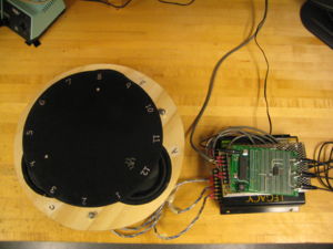
Vibratory Clock
Team Members
- Jennifer Breger - Mechanical Engineering Class of 2009
- Brian Lesperance - Electrical Engineering Class of 2008
- Daniel Pinkawa - Mechanical Engineering Class of 2008
Overview
We built a horizontal circular platform that is actuated from underneath by three speakers placed in an equilateral triangle. The vibration of the platform causes a small object (e.g., an IC socket or a coin) to act as an hour "hand" on top of the platform. The object slides around the circular platform, impelled by friction forces due to the vibration. By placing the speakers at different phases and amplitudes, we got the objects to move to desired positions. Due to the nodes created by the speaker vibrations, the object will move back to the correct hour if it is moved away. Our project was given to us by Professor Colgate and was based upon the research of Professor Lynch.
Theory
Through his research, Professor Lynch found that when a pivot point is placed under a platform that is attached to speakers, sinks and nodes can be created by places speaker vibrations at different amplitudes and phases. Applying his research to our project, it was determined that if we placed two speakers at equal amplitudes and opposite phases, a sink would be created in between the speakers. This result can be thought of as the center being the center of a teeter-totter, in which two people of equal mass but at completely opposite phases would cause the teeter-totter to rotate perfectly around the center pivot point. However, if the two speakers were at equal amplitudes and perfectly in phase with each other, that side of the plate would move up and down in one motion, causing the sink to be at the other side of the plate.
We found that if we alternated between two different phases that created two orthogonal sinks, we could create a node at the intersection. For example, if we wanted to create a node at 12 o'clock, we would alternate between the radial and orthogonal phases. In the radial phase, we created a sink along the diameter of the plate between the two speakers that were not at 12 o'clock, namely speakers B and C. Using the theory of creating sinks, we placed speakers B and C at equal amplitude and 180 degrees out of phase with each other. If several small objects were placed on the plate at this point, all the objects would converge to the central line of the plate. Next, in order to create the orthogonal sink that would create a node at 12 o'clock, we placed speakers B and C in phase and at equal amplitude. However, in order to counteract the forces from speakers B and C, we put speaker A (the speaker at 12 o'clock) at a weak amplitude and 180 degrees out of phase with speakers B and C in the orthogonal phase.
This same notion was the used to create all of the even number nodes on the clock face. In order to create the nodes at the odd numbers, we slightly changed the amplitudes of the speakers at the previous time until the correct placement was found.
Although theoretically our design should have allowed us to program the clock using symmetry, due to slight imperfections in the design and in the electrical components, we had to use some trial and error methods to place the nodes correctly. Nonetheless, the theory allowed us to create nodes almost exactly where we wanted them to be.
Mechanical Design
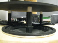
The Vibratory clock consists of a wooden base, held up by adjustable legs, three speakers, and a circular platform. The following material were used to create the design:
Base:
- wood: 16" diameter, 0.75" thick
- holes: 6" diameter (3 total)
- adjustable legs: 3 rods: 3/8"-16; 4" long; 6 nuts total
Speakers:
- 3 Pyramid Power PW677X: 300W, 4 Ohms, 6.5" Chrome Subwoofer
- previously adapted speakers replaced center of speaker with attachments 3" in height and 1/2" hole on top
- 1/2" diameter PVC used to attach previous attachment to platform with a screw
- held in place by 2 set screws each
- centers placed 7.125" apart
Circular Platform
- PVC/Acrylic: 11.75" diameter, 0.25" thick
- machined on the LaserJet
- screw holes counter-sunk at 7.125" apart
- 2.875" above wooden base
- Silver Sharpie used for numbers
Reasoning for Geometry of Design
Equilateral Triangle: By having the speakers equidistant from each other, we were able to create symmetry in our design, which made programming the various nodes much easier. For example, we were able to use the same theory to find the node at 12 o'clock, 4 o'clock, and 8 o'clock. If the speakers were not placed equidistant from each other, two speakers placed at equal amplitudes and opposite phases would not have created a sink in the exact middle of the two speakers.
Adjustable Legs:
We needed to make the legs adjustable since it is essential that the platform be perfectly level in order for the objects placed on the platform to move in expected patterns. For example, if one leg is slightly shorter than the other two, the objects placed on the platform would tend to move towards that leg and we could no longer rely on symmetry to program the various nodes due to the effects of gravity.
Height of Platform:
Through our own experimentation and from Professor Lynch's research, we found that we needed to have the pivot point (i.e. the speaker diaphragm) significantly below the platform in order to create sinks. At one point in the design process, we attempted to create a different pivot point by replacing the PVC with 1/2" outer diameter, 1/4" inner diameter Tygon 2001 tubing that only was able to bend in one point since it had stand-offs and screws inside the tube. However, this replacement in a sense created two pivot points (the speaker diaphragm and the Tygon), causing the platform to only create sources and not sinks. In addition, the different height of the pivot point may have also led to the plate acting differently.
Electrical Design
Component List:
| Part | Part No. | Qty | Vendor | Price (Total) |
|---|---|---|---|---|
| Microchip 8-bit PIC Microcontroller (U1) | PIC18F4520 | 1 | N/A | N/A |
| Maxim Quad, 2-Wire Serial 8-Bit Digital-to-Analog Converter (U2) | MAX520 | 1 | Digi-Key | $9.28 |
| Emtel 150W, 12V Power Supply | EMV15012V | 1 | N/A | N/A |
| Emtel EMV15012V Wiring Kit | 61-EMV15012VWK | 1 | N/A | N/A |
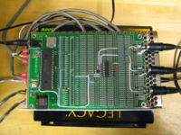
| Legacy Series II 4-channel, 300W Power Amplifier | LA160 | 1 | N/A | N/A |
| Keystone Electronics Snap-Fit 90 PC Phono Jack | 901K-ND | 3 | Digi-Key | $3.81 |
| Radioshack 6-Ft. Shielded Cable, RCA Plug to RCA Plug | 42-2367 | 3 | Radioshack | $14.97 |
| 20-ft Monster Cable 16-Gauge Speaker Wire | S16-2XLN | 1 | Radioshack | $9.97 |
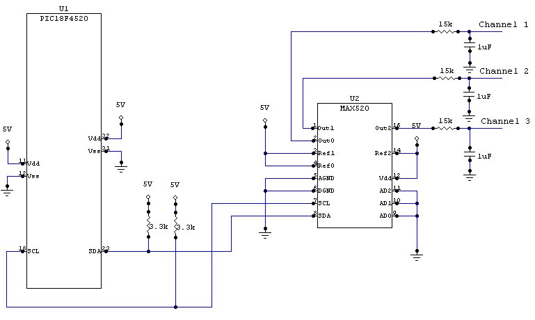
Circuit Diagram:
Software Design
Results
We were able to get our project working so that the plate moves an object placed anywhere on the plate to the correct time and then moves the objects around the clock face, acting as the hour "hand" of a clock. However, we increased the speed so that it takes about 2 minutes for objects placed on the clock to move around so that it is easy to demonstrate. Check out the working Vibratory Clock HERE.
Reflections
Useful Resources
Vibration-Induced Frictional Force Fields for Part Manipulation
