IR communication between PICs
Overview
Two PICs can easily communicate with one another using serial communication. IR communication is a basic extension of this method which can be easily implemented with a microcontroller (PIC) through an IR Encoder/Decoder (endec) and an IR Transceiver. The endec and transceiver used in this example support Serial IR (SIR) data rate, ranging from 9.6 kbps to 115.2 kbps. The typical range of the transceiver is nominally from 2 inches to 2 feet and extends upwards of 12 feet. The PIC, endec, and transceiver employed all support bidirectional use. However, when a transceiver is transmitting it essentially blinds its receiver and therefore cannot attain true full-duplex communication; only half-duplex was used with the transceiver taking turns transmitting and receiving.
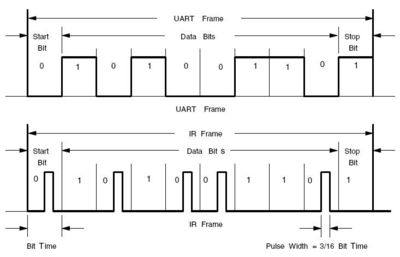
When transmitting, the PIC sends the serial format data to the endec, which encodes (or modulates) it bit by bit. This encoded data is then outputted as electrical pulses to the transceiver. The transceiver converts these electrical pulses to IR light pulses. When receiving, the transceiver receives IR light pulses (data), which are outputted as electrical pulses. The endec decodes (or demodulates) these electrical pulses, with the data then being transmitted by the endec UART back to the receiving PIC. This modulation/demodulation method is performed in accordance with the IrDA standard.
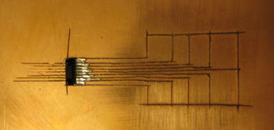
Both the PIC and the endec used in this example were DIP packages, making them easy to prototype and inspect. The transceiver, however, was a surface mount chip with an uncommon pin configuration (0.95 mm pitch), requiring a different mounting approach. We initially attempted to etch a copper-clad board for our circuit (see image). Another possible solution for our transceiver is provided by SchmartBoard. These boards are more general and pre-fabricated for use with surface mount ICs (with a particular pitch or pin seperation). Both solutions will allow for connections to a solderless breadboard.
Circuit
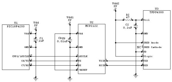
The circuit diagram below shows a complete half-duplex IR communication circuit. This circuit can either be used together with an identical circuit to communicate, with only one PIC transmitting at a time, or with a remote control. The software on the PIC can be configured to respond to a variety of commands sent by the remote. The electrical characteristics of the power supply and discrete components are given below. Some of the ranges for the IR circuitry are also given below in parentheses. In the circuit, there are two interfaces: the serial interface and the IR interface.
Serial Interface
The serial interface is located between the PIC and the endec. The transmit (TX) and receive (RX) pins on the endec need to be connected between both ICs with a common ground. The data passing between the two components on these lines have the standard 8-N-1 serial data format. There is also a 16XCLK signal going to the endec from the PIC used to control the baud rate of the endec; that signal is a square wave pulse train at a frequency of 16*(the baud rate) and is generated in software. The RESET signal on the endec could be controlled with software but is simply held high since the endec need not be reset.
IR Interface
The second interface — the IR interface — is located between the endec and the transceiver. This interface is straightforward with the TXIR and RXIR pins of the endec connecting to the TXD and RXD pins of the transceiver, respectively, and also has a common ground. The signals between these two components conform to the IrDA physical layer standard. When a logic high or '1' is to be transmitted, a logic low will be sent to the transceiver. When a logic low or '0' is to be transmitted, a logic high will be pulsed after 7-8 cycles of the 16XCLK signal for 3 cycles of the 16XCLK signal but no longer than 4 µs.
Electrical Characteristics
Microcontroller (Microchip PIC18F4520)
- VDD = 5.0V
- C1 = 1µF
- VDD - Pin 11 & 32
- GND - Pin 12 & 31
- TX - Pin 25 (C6)
- RX - Pin 26 (C7)
- 16XCLK - Pin 17 (C2/CCP1)
IR Encoder/Decoder (Microchip MCP2122-E/P)
- VDD = 5.0V (1.8V-5.5V)
- CBYP = 0.01µF
IR Transceiver (Vishay TFDU4300)
- Vcc1 = 5.0V (2.4V-5.5V)
- Vcc2 = 5.0V (-0.3V-6.0V)
- Vlogic = 5.0V (1.5V-5.5V)
- R2 = 47Ω
- C2 = 0.1µF
Surface Mount Prototyping
- Transceiver lead pitch = 0.95mm
- Multiple options for installation
- Schmart board
- Digikey board (need to find)
- Copper-clad board etching
Limitations
- IR Communication is only Half-Duplex (only one transceiver transmitting at a time)
- Transmission Distance maximum is about 12 feet (about 3ft in low power mode)
- Communication Speed can only go up to 115.2 kpbs
Code
Example code for a simple IR communication circuit w/o the use of a transceiver:
/*
  ircomm.c Jennifer Breger, Brian Lesperance, Dan Pinkawa 2008-02-05
  Using the PIC's built-in UART, a counter continually is sent to one IR encoder/decoder.  Then
  the first IR encoder/decoder feeds its TXIR to the RXIR of a second IR encoder/decoder.  The
  second IR encoder/decoder then transmits back to the PIC what it is receiving.  When the
  transceiver circuit is properly mounted and inserted into the circuit, this code can be adapted
  for half-duplex communication w/ another IR communications circuit.
*/

#include <18f4520.h>
#fuses HS,NOLVP,NOWDT,NOPROTECT
#use delay (clock=20000000)
#use rs232(baud=9600, xmit=PIN_C6, rcv=PIN_C7, stream=com_a) // Initializes the UART to 9600 bps
                                                             // (up to 115,200 bps)

// timed_getc() checks whether data is ready to be read.  If it's not the function returns a null
// character.  If you simply use getc(), the PIC might get slowed up if the data isn't ready right
// away.
char timed_getc(void){
   long timeout;
   int timeout_error = FALSE;
   timeout = 0;
   while(!kbhit() && (++timeout<50000))
      delay_us(10);
   if (kbhit())
      return(getc());
   else {
      timeout_error = TRUE;
      return(0);
   }
}

// Main program
void main(void){
   int i;
   char rx;

   setup_timer_2(T2_DIV_BY_1, 32, 16); // Provides a 151.3 kHz clock for the Encoder/Decoder, in
   setup_ccp1(CCP_PWM);                // order for it to know the baud rate of the UART. Should be
   set_pwm1_duty(16);                  // closer to 16 * 9600 = 153.6 kHz but the error is tolerable

   while(TRUE){
      for(i=0;i<16;i++){      // Counts up from 0 to 15 and transmits to the first Encoder/Decoder.
         putc(i);             // Listens to the second Encoder/Decoder, which is simply the original
         rx = timed_getc();   // message from the PIC, and displays the value on the LEDs/Port D.
         output_d((int8) rx);
         delay_ms(1000);
      }
   }
}


