Microphones
Original Assignment
This project is to demonstrate a "clapper" device using an electret microphone (e.g., the 423-1024-ND from digikey). Build an appropriate circuit and write a program to continuously display the volume of the sound it receives as a "light bar" on the PIC board LEDs.
Overview
A "clapper" device will be built using a PIC 18F4520 and to take various audio analog inputs. An electret microphone (in this case, the 423-1024-ND from digikey) was used to pick up the external sound and send it to the PIC. The device operates on the principle that as the sound increases in volume, the audio input's frequency will increase. This input is received by the PIC and converted into an output on a set of LED displays that were originally placed on a circuit board (as shown). This output emits the minimum one LED for minimal sound levels as an input to all 7 LEDs for the maximum input that the PIC can receive.
Due to the nature of possible ambient noise, a calibration "reset" button was placed that would reset the output LEDs to the minimum surrounding sound. This calibration was done via software. The device that is built currently follows the principles of the "clapper" device in that the higher the analog input is received, the more LEDs will be shown. However, due to the brevity of the audio input frequency itself, for shorter audio signals received it is difficult for the LEDs to display the signal. A further step would be to extend the time that each LED displayed.
Circuit
The circuit built for this example uses an electret microphone to listen to external sound and displays the volume level as a light bar on the PIC board LEDs. The microphone uses a single analog input pin of the PIC.
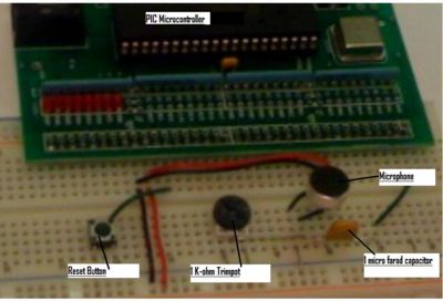
Optional features present in the shown circuit diagram include a potentiometer gain knob for adjusting the microphone's sensitivity and a calibration button for setting the baseline ambient noise level. The code governing the operation of the calibration button is included below; the button itself is wired into a digital input of the PIC.
| This is a photo of the circuit. |
| This will soon be an image of the circuit diagram. |
Code
/*
microphone.c by JJ Darling, Alex Leung, Ben Schriesheim
This code will take an analog microphone input and display the power of the single
as an easily read LED array. One light on means the input matches the ambient noise,
and all eight lights on means the microphone is receiving a loud noise.

The reset button can be used to match the lowest output to the ambient noise.

This code was derived off of the analog input code written by Prof. Michael Peshkin, which
can be found in the source code repository on this wiki.
*/

#include <18f4520.h>

#DEVICE ADC=8                  // set ADC to 8 bit accuracy.

#fuses HS,NOLVP,NOWDT,NOPROTECT
#use delay(clock=20000000)

int16 valuebuff[100];      // Initialize variables
signed int16 value;
int32 valueinit=0;
int k=0;
void initialize();

void main() {

   initialize();
   setup_adc_ports(AN0);        // Enable analog inputs AN0;
   setup_adc(ADC_CLOCK_INTERNAL);


   while (TRUE) {
      if (input(PIN_C0)>0)  initialize();   //Initialize the base output to match ambient noise

      set_adc_channel(0);     // there's only one ADC so select which input to connect to it; here pin AN0
      delay_us(10);           // wait 10uS for ADC to settle to a newly selected input
      value = read_adc();     // now you can read ADC as frequently as you like

      //Create a gain to dramatically differentiate the input level from ambient noise
      if ((value-valueinit)<0) value=0;
      value=(value-valueinit)*4;

   if (value<32)              //Easy to read volume meter
      output_d(0b1);
   else if (value<64)
      output_d(0b11);
   else if (value<96)
      output_d(0b111);
   else if (value<128)
      output_d(0b1111);
   else if (value<160)
      output_d(0b11111);
   else if (value<192)
      output_d(0b111111);
   else if (value<224)
      output_d(0b1111111);
   else if (value<1000)
      output_d(0b11111111);

   delay_ms(10);
   }
}

//Take samples to establish an initial value to 'tare' the ambient noise.
void initialize() {

   delay_ms(1000);       //Give enough time for the user to release the "reset" button

   valueinit=0;

   //Read 100 input levels and take their average. This a measure of the ambient noise
   for (k=0;k<100;k++) {
      set_adc_channel(0);
      delay_us(10);
      valuebuff[k] = read_adc();
      valueinit+=valuebuff[k];
   }
   valueinit = (valueinit/100);

}
