Photodiodes and Phototransistors
From Mech
Phototransistors
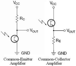
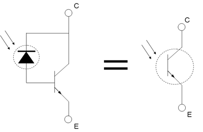
Phototransistors are transistors with the base terminal exposed. Instead of applying a voltage to the base, the photons from striking light activate the transistor. Other than that, the phototransistor behaves just like a normal transistor. Two common configurations are shown on the right.
- Common-Emitter Amplifier - goes from "high" to "low" with light.
- Commond-Collector Amplifier - goes from "low" to "high" with light.
The phototransistor can be used in two different modes: 1) active & 2) switch. These modes are controlled by changing the value of the resistor. The equations are:
Fairchild recommends a 5kohm resistor or greater to use as a switch
- Switch Mode - when operating as a switch, the transistor can be switched between the cut-off ("off") and saturated ("on") states. This means that when light strikes the phototransistor, it will conduct. Otherwise, it will insulate.
- Active Mode - In active mode, the output of the transistor is proportional to the intensity of the light.
Photodiodes
Photodiodes are semiconductors that produce current flow when they absorb light. In application, there are two types of photodiodes: 1) photovoltaics and 2) photoconductors.
- Photovoltaics
- Photovoltaics work like solar cells (in fact they are the same). When light shines on the photodiode, a voltage is created across it, causing current to flow.
- Photoconductors
- Photoconductors are reverse-biased photodiodes. When light shines on the photodiode, the resistance to the reverse-bias decreases. By measuring the current through the photodiode, you can detect the intensity of light.
Comparison
- Frequency Response
- Photodiodes are much faster than phototransistors
- Gain
- Phototransistors have a higher gain
Applications
- Optocoupler
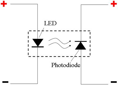
- Optocouplers are used in electronics-sensitive applications. For example, you may use this in a mobile robot application to separate the microcontroller circuitry (low voltage/power) from the motor driver circuitry (high voltage/power).
References
- Fairchild Semiconductor, "Design Fundamentals for Phototransistor Circuits," PDF,


