555 Timer
From Mech
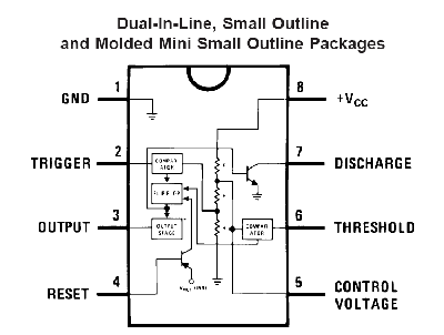
Jump to navigationJump to searchConnection digram for the 555 IC timer (click for larger image).
Inside the 555 timer is a voltage divider the divides +VCC into thirds. A voltage comparator compares the trigger input (pin 2) with 1/3 VCC, and another comparator compares the threshold (pin 6) with 2/3 VCC. The point at 2/3 VCC on the voltage divider is connected to the control voltage (pin 5). This pin can be used to modify the values of 1/3 VCC and 2/3 VCC without having to change VCC. However, if this input is not going to be used, it should be connected to a bypass capacitor (0.01uF) to protect it from noise.
Monostable and Astable mode
The 555 family of timer chips can be used in either monostable mode or astable' mode.
