555 Timer
From Mech
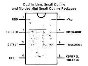
Jump to navigationJump to searchInside the 555 timer is a voltage divider the divides +VCC into thirds. A voltage comparator compares the trigger input (pin 2) with 1/3 VCC, and another comparator compares the threshold (pin 6) with 2/3 VCC. The point at 2/3 VCC on the voltage divider is connected to the control voltage.
Monostable and Astable mode
The 555 family of timer chips can be used in either monostable mode or astable' mode.
