Northwestern Design Competition
From Mech
DC2012
Equipment
- NU32, USB cable, 6V power supply
- 2 drive motors, 2 motor mounts, 2 wheels
- 2 large RC servos, 2 small RC servos
- red lasers
- 2 12"x24"x1/8" acrylic sheets
Workshop 1, Wednesday 1/18 5:30-7pm Tech L221, makeup Thursday 1/19 9-11am Mechatronics Lab
- How to program in MPLABX
- How to use the bootloader to put code on the NU32
- Digital output I/O (read a button and flash an LED)
- Analog input
- PWM output
- Sample code: Sample code for Workshop 1
Milestone 1, due by 1/27
- If a pushbutton is pressed, read the value of a potentiometer and change the brightness of an LED to the corresponding value with PWM
Workshop 2, Thursday 2/9 6-7pm Tech L221, makeup Friday 2/10 9-11am Mechatronics Lab
- Optical isolation for motors and RC servos
- Powering a motor with an h-bridge
- Writing to the 16x2 character LCD
- Laser detection of retroreflective tape / Optical line detection
- 2 1/2D design
Milestone 2, Due week of Feb 27
- Optically isolate a motor
- Read a potentiometer and write its voltage to the LCD
- Control the motor velocity based on the potentiometer reading
- Control an RC servo
- Detect a 3/4" wide black line on white paper with a phototransistor and LED
Workshop 3, Week of Feb 27
- Line following
- Laser cutting
- Line following and detecting the crate
Milestone 3, Due week of Mar 5
- Finish laser cutter training
- First draft of a robot chassis
- One of the following:
- Follow a line
- Detect a crate or scoring zone and drive towards it
DC2011
Milestone 1
- On a button press, read the value of a potentiometer and change the brightness of an LED accordingly using PWM. Note: Do not use an h-bridge or motor as previously assigned.
- Due before Workshop 2 on Wed, 2/9.
- Sample code from Workshop 1
Milestone 2
- Due before Workshop 3 on Wed, 2/23.
- Goals:
- Use code from NU32v2: Nokia 5110 LCD and NU32v2: Analog Input to read a potentiometer and print the voltage to the Nokia 5110
- Optically isolate a motor and control its velocity based on the potentiometer reading
- Do 1 of the following:
- Mount a phototransistor to a laser and detect a cake OR
- Detect a line of electrical tape on white paper with an optoreflector
- Datasheets
- HBridge_L293D.pdf - H-bridge for driving a DC motor
- Optocoupler_A847.pdf - Optocoupler to optically isolate your H-bridge
- HexInverter_74HC04.pdf - Inverting chip to digitize optocoupler output
- Optoreflector_OPB740.pdf - Optoreflector to detect lines or color
- Optoreflector_QRE1113.pdf - Optoreflector to detect lines or color
- Phototransistor_SFH310.pdf - Phototransistor to detect lines, color, or laser reflections
- Notes
- DC2011_WS2_OpticalIsolation.pdf - How to optically isolate an h-bridge and servo motor using the A847 and 74HC04
- DC2011_WS2_OpticalSensors.pdf - How to use the SFH310 to detect a cake and use the OPB740 or QRE1113 for line following
- DC2011_WS2_Code.zip - Example code for the NU32v2 that will:
- Control a DC motor hooked up to an optically isolated h-bridge, and control an optically isolated RC servo motor
- Respond to serial commands to control the motors, write to the Nokia 5110, and read two analog signals
Milestone 4
- Due before Wed, 3/16
- Finish laser training, at least one person per team
- Construct a prototype chassis for your robot
- Do one of the following:
- Follow part of the line on the 36" x 96" printout of this pdf
- Detect a cake somewhere on the floor and drive to it
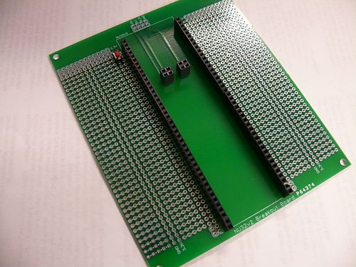
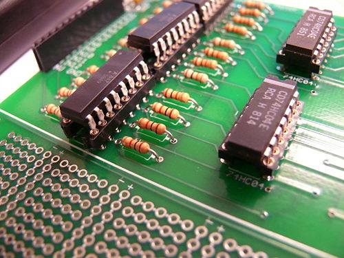
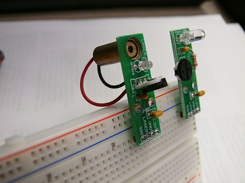
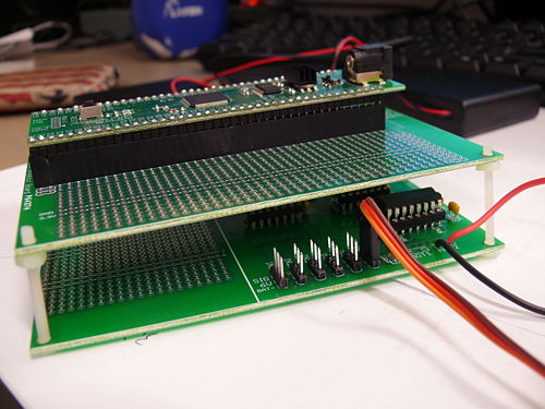
Breakout Boards
- Image of the breakout boards
- Circuit schematic of the breakout boards
- This board contains:
- A spot to plug in the NU32v2 with some prototyping area
- The optical isolation circuit with some prototyping area, the same size as the NU32v2 breakout board so it can be stacked on top
- 8 SFH310 with LED breakout boards
- 4 SFH310 with laser diode breakout boards
- 1 LIS352AX accelerometer breakout board
- 1 LSM303DHL tilt-compensated compass breakout board
- 1 LPY550AL gyroscope breakout board
- 1 LS7366R encoder decoder breakout board
- 1 TCS3103 color sensor breakout board
- How to use the boards:
Brochure for 2011
Previous Years
Wiki pages on sensors, actuators, programming, and microcontrollers: use pages below
- Parts in the DC2008 quick start pack
- PIC C intro slides, as presented 2008/01/24 (pdf)
- PIC interfacing slides, as presented 2008/01/28 (pdf)
- Link to all sample PIC code here.
Sensors and actuators for DC
- Solderless Breadboard & wiring that works
- Using LEDs & IREDs
- Using a laser
- Infrared reflectivity
- Using phototransistors
- Sensing optical tape
- Comparators : the analog digital interface
- Faulhaber MiniMotor SA gearmotor with encoder, as well as the local wiki page
- Adding a magnetic encoder to a GM3 Gearmotor
- Using magnetic switches (Hall Effect)
- Driving high-current devices: several options
- Driving a Stepper Motor
- Driving an RC Servo
- Accelerometers
- Strain gauges
- Basic Stamp Microcontroller Not recommended for DC2008
- NiMH rechargable batteries and chargers
Prof. Peshkin's favorite datasheets


