Music from the Heart -- Music Suit
Introduction
This project attempted to create a natural form of musical expression by connecting sensors to the body. Six tilt switches were attached to the wrist, ankles, and shoulders, each controlling a single pitch from the pentatonic scale. The heart beat was obtained using photoplethysmography on the user's finger, and this signal was used to strike a drum in sync with the heart beat.
Team Members
- Thomas Peterson (Computer Engineering, 2010)
- James Rein (Biomedical Engineering and Music Cognition, 2010)
- Eric West (Mechanical Engineering, 2011)
Subsystems
Although intended as a single, cohesive system that would allow the user to intuitively make music, the project was easily divided into three subsystems: heart rate monitor, drum actuation, and music tones. Below is more explanation about each subsystem.
Heart rate monitor - Concepts
In brainstorming how to translate a heart beat into a drum beat, we decided that the least intrusive method would be the best. Attaching electrodes to the user would simplify the process of identifying a heart beat, but attaching the sensors directly to the skin would be a time-consuming and personally-invasive process. Instead, we decided a finger tip sensor would be much more comfortable and easy to use.
To make a finger tip sensor, we used the concepts of photoplethysmography. Photoplethysmography is typically used in pulse oximeters and finger-tip sensors in commercially-available devices. We originally tried to hack a heart rate monitor that we had purchased, but this proved difficult, so we decided to make our own.
The basic concept of photoplethysmography is that blood reflects a certain amount of IR light, and the blood density in the finger changes as the heart pumps, so the IR reflectivity of the finger changes as the heart beats. Using an IR emitter-detector pair found in the mechatronics lab followed by lots of amplification and filtering, we were able to obtain a decent signal with peaks when the user's heart beat.
Heart rate monitor - Electrical Design
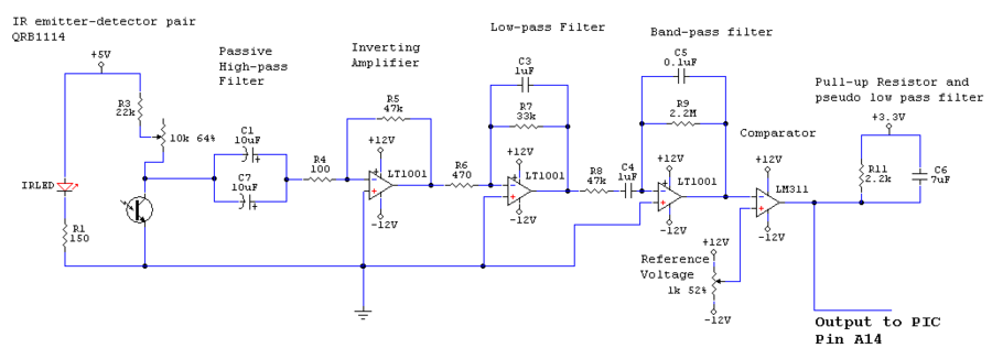
The signal coming directly out of the IR detector was very weak and noisy. To obtain just the information we desired, we ran it through the following filters and amplifiers:
- Passive High-Pass Filter
- Inverting Amplifier: gain = -470
- Active Low-pass filter: cutoff frequency = 4.82Hz, gain = -70
- Band-pass filter: Frequency range = 0.72 to 3.39Hz, inverting gain = -46.8
- Comparator: output to the PIC pin A14, with pull-up resistor to 3.3V and capacitors to smooth out the signal.
The complete signal processing circuit is shown below.
Heart rate monitor - Mechanical Design
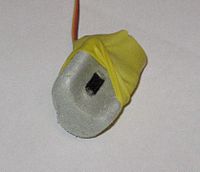
The sensor itself was a QRB1114 emitter-detector pair that was encased in open-cell foam insulation. We inserted it into the foam by drilling and filing a hole in the foam to the appropriate size, and gluing the sensor in place. A round, finger-shaped groove was filed into the foam and the sensor sat flush with the bottom of this groove. The user's finger was held in the correct position with relatively constant pressure using a latex band around the finger and the foam enclosure.
Drum actuator - Electrical design
Once the signal from the heart rate sensor is sent to the PIC, the rising edge triggers an interrupt which starts the driving sequence for the motor that strikes the drum. The drive sequence was: drive down (into drum) 100ms, drive up 75ms, wait 150ms. The interrupt does not do the entire driving sequence, it merely flags a variable to start the sequence, which is done in the main loop, as seen in the code below.
An additional interrupt was triggered by the falling edge of the signal; this falling edge interrupt added additional wait time that prevented the PIC from being "fooled" by a noisy falling edge. For instance, if the falling signal had some noise in it, the rising edge interrupt would be triggered again, thus causing the drum to strike on both the rising and falling edges of the heartbeat. We only wanted one strike per heartbeat, so the falling edge interrupt was triggered by the first falling edge, and any noise in the falling edge was ignored because the PIC was told to wait for 300ms. With a maximum delay of 150 + 300 = 450ms from the two interrupts, the fastest heartbeat our drum could play was 133 beats per minute, but we did not expect anyone to come play the instrument after running, so this was plenty high for our purposes.
Initially, we tried skipping the comparator and sending the analog signal directly into one of the PICs analog inputs. Our intention was to use the fast Fourier transform (FFT) library to try to extract the dominant frequency. Unfortunately, we ran into various problems. First, to get the accuracy we wanted for small frequencies, the sample window had to be very long (10 seconds or more), which made the output lag changes in heart rate. Additionally, the FFT was often "messy", which messed up our original algorithm of detecting the peak frequency between .5 and 2.5 hz. The system would sometimes randomly switch between very different frequencies, and although it was right most of the time it was enough to make the drum beating sound bad. We also tried algorithms to find the fundamental frequency using the entire FFT (instead of just the .5-2.5 hz range), but this was still unreliable. We considered FFT peak detection algorithms, but they seemed to complex for the time and computing power we had available. Because of all this, we went with the simple comparator in the end.
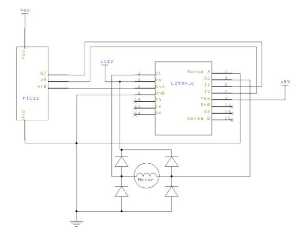
The motor for driving the drumstick was driven by an L298 H-bridge. See Driving a high current DC Motor using an H-bridge for more information on how this works. Our particular circuit diagram is shown below:
Drum actuator - Mechanical Design
We wanted to use a real drum for our drum beat, so our challenge was to attach a motor and drumstick to a drum. We chose a small rack tom for its resonant tone that is reminiscent of a heart beat.
To attach the drumstick to the motor shaft, we used a small block of acrylic (.5"x.5"x2"). The drumstick was cut down to 8" in length so that it would require less torque from the motor. In one end of the block, a hole was drilled and the drumstick was sanded to the correct diameter in order to snuggly fit into the hole. To ensure that the drumstick could not slide out of the block, a screw was placed in a hole drilled through both the stick and the block. The other end of the block was attached to the motor shaft using a split-clamp method: A hole the size of the motor shaft was drilled through the block, and then a slit was cut from the end of the block to the hole, allowing a screw to tightly clamp the block around the motor.
INSERT PICTURE OF DRUMSTICK-MOTORSHAFT ATTACHMENT
To attach the motor-stick assembly to the drum, we utilized the tuning screws on the drum. A sheet metal bracket with holes in the appropriate places attached the motor to two of these tuning screws. The bracket was easily made by cutting and bending a piece of 16 gauge steel sheet metal to the appropriate size. Ideally, this part would have been made out of one continuous piece of sheet metal, but we could not find a large enough sheet available in the shop, so we used rivets to connect two smaller pieces together.
After testing the drum striking, we decided it was too loud. To dampen the sound, we taped a piece of foam core and a shop rag to the head of the drum where the stick strikes it.
Parts list for drum actuator
- Bargain drumstick, at least .5" in diameter
- Small block of acrylic, .5"x.5"x2" (aluminum would work just as well, this is what was available)
- 16 gauge steel sheet metal for bracket
- Screws and nuts
- Foam core, shop rag, tape for dampening
Music Tones - Electrical Design
The music tones were activated by tilt switches and generated using a YMZ284 chip and were output through a 1/8" jack to a standard set of computer speakers.
Each YMZ284 is capable of producing and mixing any combination of three tones. Since we wanted to have six notes from a pentatonic scale, we needed two of these chips and used an summing opamp circuit to combine outputs from each chip. We envisioned a possibility of adding overtones to each note, to make them sound better and more like a real instrument, so we ended up having four YMZ284s attached to our board. When we tried adding an overtone an octave above the fundamental frequency, it ended up sounding harsh and whiny. We decided the tones sounded better with no overtones, so we are only using 2 of the 4 chips on our board.
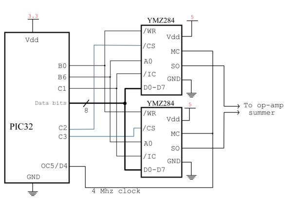
The YMZ284 communicates with the PIC over an 8-bit databus, plus additional pins for chip select, address, write enable, and reset. All four of our YMZ284s shared all of their pins except the chip select line; each required their own individual chip select line so that the PIC could specify with which chips it wanted to talk. The circuit diagram below shows how the chips were connected to the PIC and the summing circuit that followed.
Tilt switches - Electrical Design
In order to detect when the limbs of the user had moved past a certain critical angle, we chose to use tilt switches. We purchased our tilt switches for $2 each from Electronics Goldmine. We chose to use tilt switches instead of an accelerometer because the switches were much cheaper and we figured they would be easier to work with.
The tilt switches we chose are optically-based with an emitter and detector that are selectively blocked by a small ball. When the critical angle is achieved, the tiny ball rolls up a ramp, allowing the emitter to shine directly on the detector, and current flows. When the angle is neutral, the ramp forces the ball to block the light, making current stop flowing through the phototransistor. The "ramp" is really an inverted cone, so the switch can be activated by a change in angle in any direction away from the neutral position. We purchased three different tilt switches to try, each with a different critical angle - 15, 30, and 45 degrees. The configuration we ended up using was:
- 30 degrees for shoulders and ankles
- 45 degrees for elbows
In hindsight, we would have used all 45-degree switches because they produced the sharpest jump from off to on. The 15-degree switches were practically unusable because they created a large amount of noise as they switched on and off.
We used the tilt switches to provide high-low inputs to the PIC to tell it when to turn on any of the six tones. By attaching these switches to the body such that they are in the neutral position when the body is relaxed, we were able to control the six tones by moving the body in relatively natural ways.
Tilt switches - Mechanical Design
The switches were attached to the user's body using adjustable straps and buckles. The wrist and ankle sensors were simply a loop of webbing with an adjustable buckle attached. The straps could be tightened or loosened to fit any size user. To attach the switch to the straps, we created an enclosure for each switch out of high-density foam (left over scraps from DSGN 307). The switch was jammed into a hole in the foam so that it could not easily be moved. The foam was then taped to the straps using electrical tape.
INSERT PICTURE OF THE WRIST AND ANKLE STRAPS
The shoulder straps were a bit more involved. Two loops with buckles, similar to the wrist and ankle straps, went over the user's shoulder and underneath their armpit. To keep these straps from sliding off the shoulders, a large strap across the user's back connected the two smaller straps together. This large strap was also used for mounting the solder board which gathered the wires from all six tilt switches and sent them to the PIC over one ribbon cable. Using this strap configuration, we found that the user could comfortably and securely wear the sensors.
To attach the switches to the shoulders, we again created a foam encasement. However, electrical tape was not secure enough to hold the foam pieces to the irregularly-shaped shoulder straps. Instead, we riveted a piece of canvas to the webbing straps. We chose to use rivets instead of sewing because the sewing machine could not tightly sew the foam encasement in place. With rivets, we were able to pull the canvas tightly around the foam so that it couldn't move.
INSERT PICTURE OF THE SHOULDER STRAPS
Code
To download the entire C file, click here. Below, the file is split into sections for comments.
/**********************************************************
 * main_music.c: Main c file for "Music Suit" project
 *
 *    Thomas Peterson, James Rein, Eric West
 *    ME333 Winter 2010
 **********************************************************/

#include <HardwareProfile.h>
#include <delays.c>  //Delayms and Delayus functions
The first section defines all the input and output pins, used with the motor, sensor, and music circuits.
////////////////////////////////////////////////////
//Pin Defines

//YMZ Chip selects
#define CS1 LATCbits.LATC2
#define CS2 LATCbits.LATC3
#define CS3 LATCbits.LATC4
#define CS4 LATGbits.LATG6
//YMZ communication pins
#define NWR LATBbits.LATB0 //"Not WRite": active low write line
#define A0  LATBbits.LATB6 //Address 0
#define NIC LATCbits.LATC1 //"Not Input Clear": active low reset line
//YMZ data pins
#define D0 LATGbits.LATG9
#define D1 LATEbits.LATE8
#define D2 LATEbits.LATE9
#define D3 LATBbits.LATB5
#define D4 LATBbits.LATB4
#define D5 LATBbits.LATB3
#define D6 LATBbits.LATB2
#define D7 LATBbits.LATB1

//Tilt inputs
#define ENC PORTDbits.RD3
#define END PORTDbits.RD2
#define ENE PORTDbits.RD1
#define ENG PORTCbits.RC14
#define ENA PORTCbits.RC13
#define ENC5 PORTDbits.RD0

//Motor outputs
#define IN1 LATBbits.LATB7
#define IN2 LATAbits.LATA9
#define EN   LATAbits.LATA10

///////////////////////////////////////
//Other defines
//Motor times
#define MS(x) x*312.5
#define DRIVETIME MS(100)
#define BACKTIME MS(75)
#define WAITTIME MS(150)
//Channels
#define CHNA 1
#define CHNB 2
#define CHNC 4


//////////////////////////////////////////
//Function definitions
void write_chip(int address, int data);
void portout(int byte);
void channelSw(int chip, int chn, int *mixer, int state);
//Global variables
int mixer1, mixer2;
int motorflag = 0;
The initialization function sets up various parts of the system.
/* init() : This function runs initializations, setting up the pic and music chips */
void init() {
   int pbClk = SYSTEMConfigPerformance(SYS_FREQ);

   /////////////////////////////////////////////
   //Setup inputs / outputs
   AD1PCFG = 0xFFFF; //All digital inputs
   TRISG &= 0xFDBF;  //sets G9,G6 to 0 (output); all else remains the same
   TRISC &= 0xFFE1;  //sets C4,C3,C2,C1 to 0s (outputs); all else remains the same
   TRISB &= 0xFF80;  //sets B0-B6 0 (output)
   TRISE &= 0xFCFF;  //sets E8,9 to output
   TRISB |= 0xF000;  //sets B12,B13,B14,B15 to 1s (inputs); all else remains the same
   TRISC |= 0x6000;  //sets C14,13 to inputs
   TRISD |= 0x000F;  //Sets D0,D1,D2,D3 to inputs
   TRISDbits.TRISD4 = 0; //Output for clock
   //Motor outputs
   TRISAbits.TRISA9 = 0;
   TRISAbits.TRISA10 = 0;
   TRISBbits.TRISB7 = 0;
   //Pulse inputs
   TRISAbits.TRISA14 = 1;
   TRISAbits.TRISA15 = 1;
   //ODC setup
   ODCCbits.ODCC1 = 1; //open drain control; can only float high (when set high) or pull low

   /* Initialize outputs */
   //YMZs
   CS1 = 1;
   CS2 = 1;
   CS3 = 1;
   CS4 = 1;
   NWR = 1;
   A0 = 0;
   NIC = 1;
   //Motor
   IN2 = 0;
   IN1 = 0;
   EN = 0;

   Delayms(100);  //wait for power supply to ramp up
   NIC = 0;       //resets YMZ284s
   Delayms(10);
   NIC = 1;
In the init() function, the pic writes all the setup data to the music chips. This includes the frequency registers, which determine the frequency of each output, the mixer, which determines which channels are on or off (1 = off), and the volume registers, which determine the volume of each channel. After the setup, the only register that is changed in normal operation is the mixer register, which merely turns channels on and off.
   //////////////////////////////////////////////////
   //Setup music chips
   //Setup Chip 1//
   CS1 = 0;
   write_chip(0x00,0xC7); //a low               // C4
   write_chip(0x01,0x01); //a high
   write_chip(0x02,0x98); //b low               // D
   write_chip(0x03,0x01); //b high
   write_chip(0x04,0x6E); //c low
   write_chip(0x05,0x01); //c high               // E
   write_chip(0x07,0xFF); //mixer (0 enables)
   write_chip(0x08, 0x0A);  //level (volume) A
   write_chip(0x09, 0x0A);  //level (volume) B
   write_chip(0x0A, 0x0A);  //level (volume) C
   CS1=1;
   //Setup Chip 2//
   CS2 = 0;
   write_chip(0x00,0x2C); //a low               //G 392
   write_chip(0x01,0x01); //a high
   write_chip(0x02,0x0D); //b low               //A 440
   write_chip(0x03,0x01); //b high
   write_chip(0x04,0xE3); //c low               //C5 523.25
   write_chip(0x05,0x00); //c high
   write_chip(0x07,0xFF); //mixer (0 enables)
   write_chip(0x08, 0x0A);  //level (volume) A
   write_chip(0x09, 0x0A);  //level (volume) B
   write_chip(0x0A, 0x0A);  //level (volume) C
   CS2=1;

   mixer1=0xFF;
   mixer2=0xFF;
OC5 is used to create a PWM signal with 50% duty at 4Mhz, in effect creating a 4Mhz square wave. This is used by the music chips as a master clock.
   //////////////////////////////////////////////
   //Setup OC to create master clock for music chips (~4 Mhz)
   OpenOC5( OC_ON | OC_TIMER2_SRC | OC_PWM_FAULT_PIN_DISABLE, 0, 0);
   OpenTimer2( T2_ON | T2_PS_1_1 | T2_SOURCE_INT, 20);
   SetDCOC5PWM(10);
The interrupts are used, as mentioned above, to control when the motor is driven. The motor should drive once every rising edge.
   /////////////////////////////////////////////
   //External interrupt setups (for motor) - INT3 (A14)
   mINT3ClearIntFlag();
   mINT3IntEnable(1);
   mINT3SetIntPriority(6);
   mINT3SetEdgeMode(1); //Rising edge
   /////////////////////////////////////////////
   //External interrupt setups (for motor) - INT4 (A15)
   mINT4ClearIntFlag();
   mINT4IntEnable(1);
   mINT4SetIntPriority(5);
   mINT4SetEdgeMode(0); //Falling edge
   INTEnableSystemMultiVectoredInt();

   /////////////////////////////////////////////
   //Setup motor timer (used for timing delays)
   OpenTimer3(T3_ON | T3_PS_1_256 | T3_SOURCE_INT, 0xFFFF);
   ConfigIntTimer3(T3_INT_OFF);
}
Main function
/* Main function */
int main()
{
   init();      /* Run initialization functions */
   Delayms(1);

   /* Main while loop: loop indefinietly */
   while (1) {
In the main while loop, the PIC checks every cycle to see if an input has changed since the last cycle. Since the "mixer" variables store the current state, if an input does not match up with its valid mixer bit then it has changed recently. In this case, the channelSw() function is called to switch on or off the music channel controlled by that bit.
      //Check for state changes in music notes
      if (ENC != (mixer1 & 0x01)) { channelSw(1,CHNA,&mixer1,!ENC); }   //If input ENC (enable C) is not equal to the state of channel A1 (note c), change the state
      if (END != (mixer1 & 0x02)) { channelSw(1,CHNB,&mixer1,!END); }
      if (ENE != (mixer1 & 0x04)) { channelSw(1,CHNC,&mixer1,!ENE); }
      if (ENG != (mixer2 & 0x01)) { channelSw(2,CHNA,&mixer2,!ENG); }
      if (ENA != (mixer2 & 0x02)) { channelSw(2,CHNB,&mixer2,!ENA); }
      if (ENC5 != (mixer2 & 0x04)) { channelSw(2,CHNC,&mixer2,!ENC5); }
During the main while loop, the motor flag variable is checked to see if the motor should be driven. If so, it enters a sequence where it uses timer3 to determine the current stage in the motor cycle, changing the outputs as needed.
      //Check for motor state changes
      switch (motorflag) {
         case 0: break;   //Do nothing (motor off)
         case 1:   //Start motor cycle
               WriteTimer3(0);   //Reset timer to 0
               IN1 = 0;          //Set H bridge to forward drive
               IN2 = 1;
               EN = 1;
               motorflag = 2;    //In drivedown cycle
               break;
         case 2:   //Drivedown cycle
               if (ReadTimer3() > DRIVETIME) {  //Wait for DRIVETIME to pass
                  WriteTimer3(0); //Reset timer to 0
                  motorflag = 3; //In driveup phase
                  IN2 = 0;       //Switch H bridge
                  IN1 = 1;
               }
               break;
         case 3:   //Driveup cycle
               if (ReadTimer3() > BACKTIME) {   //Wait for BACKTIME to pass
                  WriteTimer3(0);   //Reset timer to 0
                  motorflag = 4;    //In coast/wait phase
                  EN = 0;           //Turn off motor
               }
               break;
         case 4: //coast / wait cycle
               if (ReadTimer3() > WAITTIME) {
                  motorflag = 5; //more wait
                  WriteTimer3(0);
               }
               break;
         case 5:  //Additional wait cycle
               if (ReadTimer3() > WAITTIME) {
                  //Done!
                  motorflag = 0; //Motor off (can now be triggered again)
               }
               break;
         //Static wait cycles
         case 6:
               if (ReadTimer3() > WAITTIME) {
                  motorflag = 7;
                  WriteTimer3(0);
               }
               break;
         case 7:
               if (ReadTimer3() > WAITTIME) {
                  WriteTimer3(0);
                  motorflag = 8;
               }
               break;
         case 8:
               if (ReadTimer3() > WAITTIME) {
                  motorflag = 0;
               }
               break;
      }

      Delayms(10);
   }
   return 0;
}//end main
Write chip function, which is a support function that writes data to the music chips.
/* write_chip: This writes the given byte "data" to the "address" (0 or 1)
               on a YMZ284. It is assumed that the chip select is already low */
void write_chip(int address,int data) {
   //Write address
   portout(address);
   A0 = 0;     //select address mode
   Delayus(1); //setup time
   NWR = 0;    //Write cycle begin
   Delayus(1); //hold time
   NWR = 1;    //Write cycle end

   //Write  data
   portout(data);
   A0 = 1;     //select data mode
   Delayus(1); //setup time
   NWR = 0;    //write cycle begin
   Delayus(1); //hold time
   NWR = 1;    //write cycle end
}
Port out function
/* port_out: This function outputs a byte to the D0-D7 port */
void portout(int byte) {
   // Note:  !! converts an integer expression to a boolean (1 or 0).
    D0 = !!(byte  & 1);
    D1 = !!(byte  & 2);
    D2 = !!(byte  & 4);
    D3 = !!(byte  & 8);
    D4 = !!(byte  & 16);
    D5 = !!(byte  & 32);
    D6 = !!(byte  & 64);
    D7 = !!(byte  & 128);
}
Channel switch function, which writes a new mixer value to turn a channel on or off.
/* channelSw: Generic channel switch function
              This writes a new mixer value to chip "chip". The mixer value
              depends on "chn", the channel turning on or off, "state" whether
              the channel is turning on or off, and "*mixer", a pointer to
              the old mixer value. */
void channelSw(int chip, int chn, int *mixer, int state) {
   /* Enable music chip */
   switch(chip) {
      case 1: CS1 = 0; break;
      case 2: CS2 = 0; break;
      case 3: CS3 = 0; break;
      case 4: CS4 = 0; break;
   }
   /* Write mixer value */
   /* This writes to channel 7 (mixer channel) the _new_ mixer value, which is
      the old mixer value with a particular bit flipped based on "chn" and "state" */
   write_chip(0x07, (*mixer) = state ? (*mixer) & (0xFF & ~chn) : (*mixer) | chn);
   /* Disable chip */
   switch(chip) {
      case 1: CS1 = 1; break;
      case 2: CS2 = 1; break;
      case 3: CS3 = 1; break;
      case 4: CS4 = 1; break;
   }

}
Interrupt functions
//External interrupt for motor driving
void __ISR(_EXTERNAL_3_VECTOR, ipl6) _SingleVectorHandler(void) {
   if (motorflag == 0) {
      motorflag = 1;   //Start motor cycle
   }
   //If on already, do nothing
   mINT3ClearIntFlag();
}

//External interrupt for motor waiting
void __ISR(_EXTERNAL_4_VECTOR, ipl5) _SingleVectorHandler2(void) {
   if (motorflag == 0) {
      WriteTimer3(0);
      motorflag = 6;   //Start wait cycle
   }
   //If on already, do nothing
   mINT4ClearIntFlag();
}
Results
The project turned out to be a mild success overall. The tilt switches worked very well for activating the music tones, but the heart rate monitor was less successful. One of the biggest issues was getting rid of very low frequency drift in the signal that made the peaks sometimes as high as 10V, but other times less 1V. Dealing with this fluctuation in peak size was the most difficult part of signal processing. As mentioned above, we tried FFT in order to establish a steady heart rate, but could not get the resolution we desired, thus we abandoned the idea.
PROBABLY NEED MORE TECHNICAL RESULTS HERE, BUT I'M NOT SURE WHAT TO SAY RIGHT NOW
The best result was that using the device was just plain fun. We each had a great time moving around and hearing the fun sounds that resulted, or if we were feeling ambitious, we would try to play a simple melody like "Mary Had a Little Lamb." It was rather difficult to play anything more complicated than that because it required lots of body control and precise movements.
Reflections
Successes
- tilt switches activated each of the six notes when they were supposed to
- the YMZ284 chips were able to produce all six notes at the same time, allowing cool chords
- tones were in tune and formed fun melodies and chords as the body moved
- drum actuator hit the drum reliably and with good tone
- heart rate monitor usually showed clear peaks on a scope, but was finnicky in practice
Room for improvements
- tilt switches sometimes bounced, so the beginning, or particularly the ends of the notes sounded jagged
- Possible Solution: add a low pass filter to the switch signal so that the signal ramps up and down.
- the shoulder straps sometimes needed adjustments for each individual in order for the sensors to be in the correct position
- Possible Solution: create straps with more constraints, such as a strap across the chest as well as the back, to ensure that the sensors are in the correct positions and orientations.
- the straps could be easier to put on
- Possible Solution: maybe integrate them into a single garment, like a onesie
- the heart rate monitor was not reliable. Low frequency drift made setting a comparison level nearly impossible, especially for more than one specific user.
- Possible Solution: improve FFT method so that desired resolution could be achieved in a short sample period (around 10 seconds). Or implement a complicated peak detection algorithm on the PIC.
JAMES SHOULD ADD SOME KIND OF HEARTWARMING CONCLUSION CUZ HE'S GOOD AT THAT STUFF
