Can Launching Fridge
Overview
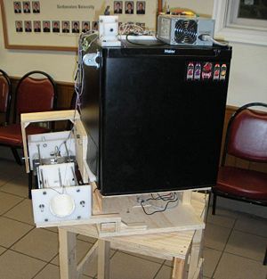
The can launching fridge is a fully automated and self contained unit designed to dispense and throw a can to a predetermined location when commanded by the user. The concept was inspired by a project done by John W. Cornwell of Duke University.
Team Members
- Derek Siegal (Mechanical Engineering, Class of 2010)
- Chris Semple (Mechanical Engineering, Class of 2011)
- Leland Gossett (Biomedical Engineering, Class of 2011)
Mechanical Design
Our design consists of three main components in addition to the refrigerator: a rotating base and stand, a launcher assembly, and an internal magazine for dispensing cans. It was decided early in the design process that we preferred a spring powered linear launch mechanism to the catapult system employed by the example mentioned above. This was for several reasons. Most importantly, this system allows for control of three parameters – launch direction, elevation angle, and power – for precise tuning and variability of the launch sequence.
Launcher Assembly
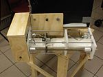
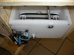
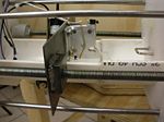
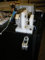
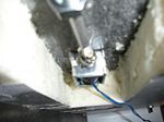
The launcher assembly is built around a polyethylene front plate connected by four steel guide rods to a box in the rear that serves as a motor mount and housing for a timing belt drive. This motor, in our case a **INSERT MOTOR SPECIFICS** stepper motor was used to turn two lead screws that run parallel and outside of the guide rods. A steel carriage plate is threaded onto these lead screws to create a linear drive capable of running the length of the assembly. In order to get smooth and reliable motion from the lead-screw drive, the alignment of the carriage had to be adjustable and the rotation had to be unimpeded. This was accomplished by machining aluminum couplers that were 3/8” - 16 threaded female on one end and exposed 1/4” rod on the other to insert into bearings. This allowed for the threaded rods to be threaded into or out of the couplers for alignment purposes, while still maintaining a constant available length. Under this was suspended half of a PVC pipe that supports the can to be launched. Finally, a launch plate is mounted on the guide rods such that it can slide freely over the pipe and these rods in the direction of launch. In action, the carriage brings forward a trigger which locks onto the rear of the launch plate. Having done so, it retracts a preset distance to store energy in the springs, and finally releases the trigger to launch the can.
Triggering the Launch Plate/Firing the Can
Controlling the Launch Angle
The whole launch assembly is mounted to the side of the refrigerator with a rear pivot point to allow cans to be gravity fed into the top of it. The launch angle is adjusted by angling this whole assembly upwards with a winch mounted on the top of the refrigerator. Though the motor for this winch was also a stepper motor, we decided to use a potentiometer for positional feedback to prevent accumulation of error through subsequent runs.
Controlling the Direction
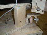
Next, a system was needed to aim the direction of launch. This is accomplished in our design by mounting the entire refrigerator on top of a turntable. This consists of a Lazy Susan bearing bolted between two plates. The first of which was bolted to the bottom of the refrigerator, while the second was elevated off the ground by a wooden frame to help reduce power required for reasonable launch trajectories. Rotation was achieved by a friction wheel driven by a small DC motor attached to the outside of the turntable plate. As with the launcher assembly, position was determined by coupling a potentiometer between the two plates.
The Magazine
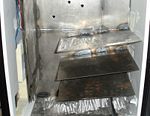
Finally, a magazine was built to feed cans into the launching tube. Placing a premium on capacity, we decided to utilize a gravity fed system essentially consisting of parallel angled plates that act as shelves for cans to rest on as they progressively feed towards an opening cut out of the refrigerator wall. All of the upper plates were cut shorter than the bottom-most one, so that a space is left for cans to roll onto the lowest plate and eventually out the opening. This magazine was welded together out of plate steel, and features a two stage loading gate. The first uses a relatively powerful and long draw solenoid that is able to overcome the friction inherent in supporting the weight of a full magazine of cans, while the second is much lighter and is positioned at the opening for the final release. This design was motivated by two considerations: first, that a single gate system would require significant tuning to time the release of only a single can, and second, that cans would potentially feed at different speeds depending on the amount of cans loaded at any given point. By using a two stage system, only enough space is permitted for one can to roll past stage one while it is open, and once stage two opens, the can will be released from a consistent distance to prevent irregularities in the sequence.
Parts List
2 x Polyethylene cutting boards, 1/2” thickness - $11.99 each from Jewel
2x Low carbon steel rods, 1/4” diameter, 6’ length – part no. 8920K11, $3.26 each from McMaster Carr
2x Acetal pulley for XL – series timing belt for 1/4" & 3/8” belt width 1.13” OD, 14 teeth – part no. 57105K14, $7.51 each from McMaster Carr
1x trapezoidal tooth urethane timing belt, .2” pitch, trade SZ 140XL, 14” outer circle, 1/4" width – part no. 1679K124, $2.75 each from McMaster Carr
2x Zinc plated steel threaded rod, 3/8” -16 thread, 3’ length – part no. 98841A031, $2.83 each from McMaster Carr
1x Lubricated corrosion resistance galvanized turntable, galvanized 6.06” square – part no. 1544T1, $5.42 from McMaster Carr
2x Pacific Scientific PowerMax II **INSERT MOTOR SPECIFICS** stepper motors - $30.00 from ebay.com
1x generic DC motor w/ gearbox and 1/4" output shaft
1x Haier thermoelectric mini fridge
30 lb test, low stretch, low memory fishing line, musky-pro series, black
9x 3/4” OD, 1/4" ID ball bearings
1.25” OD aluminum bar stock, approx 1’ in length
4x 4” extension springs
3” PVC pipe, approx. 16” in length
Various wood: 3/4" and 1/4" plywood, 2’ x 4’ wooden beams for the base
3” OD, 1/4" ID rubber wheel
3x pull type solenoids
Electrical Design
The control system for our project was centered around a PIC32MX microcontroller in a NU32 breakout board designed and proved by Northwestern University. In total, the electrical system included six actuators and four sensors: two stepper motors, one DC motor, three solenoids, two limit switches, and two potentiometers.
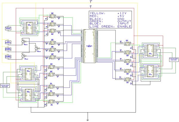
As described previously, stepper motors were used for the cocking mechanism and elevation winch so as to easily provide stationary holding torque necessary for both of these applications. These were each driven by two L293D dual H-bridges, with one chip driving each motor phase. This was done because we were unable to get reliable operation out of the larger available H-bridges, but a single L293D chip could not provide the amount of continuous current required by the motors. As shown in the circuit diagram, channels one and four as well as two and three were tied together to recreate one more robust H-bridge per chip. Similarly, the enable pins for all of the chips were tied together to allow the entire motor to enabled or disabled with one logic line. The DC motor was controlled similarly, though one L293D was sufficient to power its coil. The solenoids were wired with one NPN transistor each. However, it was discovered during testing that the current drawn by these transistors and H-bridges was enough to cause drops in the five volt logic supplied to the PIC, leading to a variety of inconsistencies in executing our control program. To address this problem, opto-isolators were added on all the digital output lines, and a separate logic supply was dedicated to the PIC.
Because this project involved relatively high torques to accomplish the aiming motions described, we were wary of relying purely on open-loop positional control. Therefore, feedback sensors were required for each of the motions performed. First, a limit switch was added to the carriage plate such that it would be closed when the carriage made contact with the launch plate, indicating to the control system that the launch plate had been latched and the loading / cocking sequence could be initiated. Next, two sensors were used for control of the elevation function. As mentioned previously, a potentiometer was coupled to the horizontal pivot axle to give an analog feedback voltage dependent on elevation. However, as this system had a small amount of slip, a limit switch was also placed under the launcher assembly to indicate when the arm was in its lowest resting position. This was done so that the motor could be disabled when it had fully lowered the assembly, and the “home” position voltage could be reset to zero to eliminate error accumulation. Finally, a potentiometer was coupled vertically through the turntable for rotational feedback. This left only one degree of freedom to open-loop control: the linear cocking distance of the launcher. While this system was not ideal, it compensated for the fact that our motors were somewhat underpowered for this application. In the case of significant motor slip, the control system would eventually signal a launch at a lesser power rather than indefinitely attempting to retract the springs against too high a load.
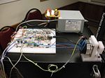
Due to the high current demands of running several motors and solenoids concurrently, a robust power supply was needed to run the electrical system. Even the bench top laboratory power supplies in the mechatronics lab were unable to fully power the largest solenoid in the project. The solution was to use a power supply taken from a laptop computer and modify it for use as a general DC power source. This method was ideal for two reasons: first, these power supplies are capable of sourcing very large currents at both five and twelve volts, and second, they are physically small enough to be attached to the designs, allowing the unit to function off of purely 120 volt AC power. For the specific procedure used to modify this power supply, see wiring a desktop power supply.
Parts List
3x 2N6045 NPN transistors – $0.81 each from Digi-Key
5x L293D dual H-Bridges - $3.92 each from Digi-Key
13x 4N27 opto-isolators - $0.59 each from Digi-Key
2x 10 kOhm potentiometers, 1/4" shaft
2x Limit switches
3x Solder-less bread boards
1x PIC32MX460F512L based NU32 microcontroller board
1x Desktop power supply and related components – see page linked above for specifics
Simerec SIS-2 IR receiver (not implemented in prototype) - $9.95
Circuit Design
If the above picture of the circuit diagram is too blurry, and a closer inspection is required, download the schematic file (in PCB artist) by clicking HERE.
C Program
Download the full code HERE.
The main control code can be found below:
//**************************************************************************************//
//******************************* BEER LAUNCHING FRIDGE ********************************//
//*******************************  ME 333 FINAL PROJECT ********************************//
//*******************************    March 19, 2010     ********************************//
//*******************************     Derek Siegal      ********************************//
//*******************************    Leland Gossett     ********************************//
//*******************************     Chris Semple      ********************************//
//**************************************************************************************//
//**************************************************************************************//
//****    This program receives a command (logic high on a CASE PIN) and then       ****//
//****    determines which case and the physical location that case corresponds     ****//
//****    to and then actuates three motors and three solenoids to do the           ****//
//****    following:                                                                ****//
//****        1) cock back a launch plate                                           ****//
//****        2) rotate the fridge to a predetermined launch angle                  ****//
//****        3) load a beer onto the launch pad                                    ****//
//****        4) winch up a launch pad to a predetermined angle                     ****//
//****        5) fire the beer by releasing the launch plate                        ****//
//****        6) return to a home position and wait for another command             ****//
//**************************************************************************************//
//**************************************************************************************//


//--------------------- INCLUDES -------------------------------------------------------
#include "HardwareProfile.h"
#include "HardwareProfile_NU32.h"
#include "stdlib.h"
#include "plib.h"
#include "string.h"
#include "stdio.h"
#include "LCD.h"
#include "motor.h"
#include "Compiler.h"


//--------------------- DEFINED CONSTANTS -------------------------------------------------------
#define ANGLE2VALUE (3.3*1024/270/2)
#define UP 1
#define DOWN (-1)
#define LEFT  1
#define RIGHT (-1)
#define NONE  0			// NMotor Error
#define FORWARD 1
#define BACKWARD (-1)
#define YES 1
#define NO 0
#define DC_STOP_POINT  (0 * ANGLE2VALUE)
#define UP_SPEED        200
#define DOWN_SPEED      300
#define FORWARD_SPEED   500
#define BACKWARD_SPEED_FAST  350
#define BACKWARD_SPEED_SLOW  150
#define START_SPEED		     25
#define HOME 0
#define STEPS_TO_INCHES  3200

//--------------------- GLOBAL VARIABLES -------------------------------------------------------
int motor1_phase;			// Winching Motor
int motor2_phase;			// Cocking Motor
int Per1; 					// Winching Motor
int Per2;					// Cocking Motor

unsigned short int elevations[3];			// vector of possible elevations, like [FLAT 15 35]
short int rotations[3];						// vector of possible rotations, like [STRAIGHT 15 -15]
unsigned short int powers[3];				// vector of possible launch strengths, like [NONE 4inches 6inches]
unsigned short int positions[2];			// [rotation; elevation]
signed short int home_position[2];			// initial potentiometer readings at startup for elevation and rotation

signed int errors[3];			// sign of the error [rotation; elevation] if the target is up, the error indicates up
int error_mag[3];				// magnitude of the error
int scenario = -1;				// which location do i want the beer at
int step_counter = 0;			// how many steps has the cocking motor taken
int quit = 0;					// am i ready to quit?
int isLatched = NO;				// YES (1) if the launch plate and cocking carriage are coupled
int step_counter2 = 0;			// For 2nd stepper, CURRENTLY NOT USED


//--------------------- Function Declarations -------------------------------------------------------
void fillCases();				// Fill elevations, rotations and powers vectors
void homePositionFill();		// Fills home_position
void getPositions();			// Get current elevation and rotation, then set error and error_mag
void getScenario();				// Program sits in this function until triggered to provide beer
void loadBeer();				// Trigger solenoid to allow one beer out onto launcher
void fire();					// Trigger firing solenoid
void loadChamber();				// Trigger large solenoid to allow one beer into storage chamber
void return_home();				// sets elevation to flat, rotation to straight


//------------------ MAIN FUNCTION -----------------------------------------------------------------
int main()
{
	// Initialize the PIC
	mInitAllLEDs();						// Flash to show startup
	homePositionFill();					// Find Home position
	fillCases();						// Fill positions and elevations
	InitMotor1();						// Initialize Motor 1
	InitMotor2();						// Initialize Motor 2
	InitDCMotors();						// Intialize DC Motors
	InitSolenoids();					// Initialize the solenoids
	motor1_phase = 0;					// Start at 0
	motor2_phase = 0;					// Start at 0


	while (1) 			// Infinite Loop
	{
		scenario = -1;
		CASE_1 == 0;
		CASE_2 == 0;

		// Determine Case
		while (scenario == -1)
		{
			getScenario();		// CALL EVENT occurs here
		}


		// Enable Interupts
		INTEnableSystemMultiVectoredInt();
		mT3SetIntPriority( 7); 	// set Timer3 Interrupt Priority
		mT3ClearIntFlag(); 		// clear interrupt flag
		mT3IntEnable( 1);		// enable timer3 interrupts ?
		mT2SetIntPriority( 6); 	// set Timer3 Interrupt Priority
		mT2ClearIntFlag(); 		// clear interrupt flag
		mT2IntEnable( 1);		// enable timer2 interrupts


		// Start Motors
		getPositions();  											// Get the current position and errors
		Turn(errors[0]);											// start turning the fridge
		Per2 = (80000000/START_SPEED)/256-1;						// start the motor at a slow speed to engage lead screw drive
		OpenTimer2(T2_ON | T2_PS_1_256 | T2_SOURCE_INT, Per2);		// start cocking motor
		Delayms(50);												// delay then:
		Per2 = (80000000/FORWARD_SPEED)/256-1;						// calculate new speed
		WritePeriod2(Per2);											// speed up the motor

		while(errors[2] != NONE)  // while launcher isn't cocked
		{
			getPositions();						// get current error
			if (errors[0] == NONE) 	Brake();	// if it's in position, stop the motor
			if (errors[2] == NONE) 				// same here
			{
				CloseTimer2();					// stop the interrupt
				motor2_enable = 0;				// this wasn't working very well, so
				StepMotor2(6);					// this line was added
			}
		}

		loadBeer();			// Load a beer
		Delayms(1500);		// Wait to let it settle

		motor1_enable = 1;											// Enable winching motor
		Per1 = (80000000/UP_SPEED)/256-1;							// Calculate winching speed
		OpenTimer3(T3_ON | T3_PS_1_256 | T3_SOURCE_INT, Per1);		// Start the motor

		while (errors[1] == UP)   // While Winching UP
		{
			getPositions(); 							// Get current position and error
			if (errors[1] == NONE)	CloseTimer3();		// stop stepping when its in position
		}

		fire();					// Fire the beer
		Delayms(3000);			// Wait a bit

		step_counter = 0;		// Reset step counter to 0
		return_home();			// Go to home position
		loadChamber();			// Load chamber

		// Turn off all LEDS
		mLED_0_Off();
		mLED_1_Off();
		mLED_2_Off();
		mLED_3_Off();

		// Turn on LED 0 to indicate ready to fire again
		mLED_0_On();
		isLatched = NO;
	}  // End of infinte while loop

} // end of main


//-------------------------------- INTERRUPTS --------------------------------------

// WINCHING MOTOR
void __ISR( _TIMER_3_VECTOR, ipl7) T3Interrupt( void)
{
	motor1_phase += errors[1];
	step_counter2 ++;
	if (motor1_phase > 3) motor1_phase = 0;
	else if (motor1_phase < 0) motor1_phase = 3;
	StepMotor1(motor1_phase);
	mT3ClearIntFlag();
}


// COCKING MOTOR
void __ISR( _TIMER_2_VECTOR, ipl6) T2Interrupt( void)
 {
	if (isLatched == YES) step_counter ++;
	motor2_phase += errors[2];
	if (motor2_phase > 3) motor2_phase = 0;
	else if (motor2_phase < 0) motor2_phase = 3;
	StepMotor2(motor2_phase);
	mT2ClearIntFlag();
}


//----------------------------------- INITIALIZING FUNCTIONS -----------------------------
void homePositionFill()  // OPEN THE ADC AND STORE CURRENT VOLTAGES AS THE 'HOME READING'
{
	CloseADC10();

				// Turn module on | output in integer | trigger mode auto | enable  autosample
	#define PARAM1  ADC_MODULE_ON | ADC_FORMAT_INTG | ADC_CLK_AUTO | ADC_AUTO_SAMPLING_ON

		// ADC ref external    | disable offset test    | enable scan mode | perform 2 samples | use one buffer | use MUXA mode
    	#define PARAM2  ADC_VREF_AVDD_AVSS | ADC_OFFSET_CAL_DISABLE | ADC_SCAN_ON | ADC_SAMPLES_PER_INT_2 | ADC_ALT_BUF_OFF | ADC_ALT_INPUT_OFF

	// 				  use ADC internal clock | set sample time
	#define PARAM3  ADC_CONV_CLK_INTERNAL_RC | ADC_SAMPLE_TIME_15

					// set AN4 and AN5
	#define PARAM4	ENABLE_AN4_ANA | ENABLE_AN5_ANA


	// do not assign channels to scan
	#define PARAM5	SKIP_SCAN_AN0 | SKIP_SCAN_AN1 | SKIP_SCAN_AN2 | SKIP_SCAN_AN3 | SKIP_SCAN_AN6 | SKIP_SCAN_AN7 | SKIP_SCAN_AN8 | SKIP_SCAN_AN9 | SKIP_SCAN_AN10
        | SKIP_SCAN_AN11 | SKIP_SCAN_AN12 | SKIP_SCAN_AN13 | SKIP_SCAN_AN14 | SKIP_SCAN_AN15

	SetChanADC10( ADC_CH0_NEG_SAMPLEA_NVREF); // use ground as the negative reference
	OpenADC10( PARAM1, PARAM2, PARAM3, PARAM4, PARAM5 ); // configure ADC using parameter define above
	EnableADC10(); // Enable the ADC

	while ( ! mAD1GetIntFlag() ) { } // wait for the first conversion to complete so there will be valid data in ADC result registers

	mInitAllLEDs();

	home_position[0] = ReadADC10(0);
	home_position[1] = ReadADC10(1);

}


// ASSIGN STANDARD POSITIONS
void fillCases()
{
	rotations[HOME] = home_position[0];								// Sets straight to startup position
	rotations[1] = (float) 10 *  ANGLE2VALUE + home_position[0];	// rotations[1] = 10 degrees left
	rotations[2] = (float) -10 * ANGLE2VALUE + home_position[0];	// rotations[2] = 10 degrees right
	elevations[HOME] = home_position[1];							// Sets flat to startup position
	elevations[1] = (float) 5 *  ANGLE2VALUE + home_position[1];	// elevations[1] = 5 degrees up
	elevations[2] = (float) 15 *  ANGLE2VALUE + home_position[1];	// elevations[2] = 15 degrees up
	powers[HOME] = 0;		// not cocked back
	powers[1] = 6 * STEPS_TO_INCHES;		// powers[1] = 6 inches
	powers[2] = 7 * STEPS_TO_INCHES;		// powers[2] = 7 inches
}


// -------------------------------------- LOCATING FUNCTIONS --------------------------------
void getPositions()
{
	// Get current position
	positions[0] = ReadADC10(0);
	positions[1] = ReadADC10(1);

	// Calculate error magnitude
	error_mag[0] = positions[0] - rotations[scenario];
	error_mag[1] = positions[1] - elevations[scenario];

	// Set motor direction for rotational motor
	if (abs(error_mag[0]) < DC_STOP_POINT)
	{
		errors[0] = NONE;

	}
	else if (error_mag[0] < 0)
	{
		errors[0] = LEFT;

	}
	else if (error_mag[0] > 0)
	{
		errors[0] = RIGHT;

	}


	// Set motor direction for winching motor
	if (abs(error_mag[1]) == 0) errors[1] = NONE;
	else if (error_mag[1] < 0)
	{
		errors[1] = UP;
	}
	else if (error_mag[1] > 0)
	{
		errors[1] = DOWN;
	}


	// Set motor direction for cocking motor
	if (isLatched == NO) // if plates arent attached, move forward until they are
	{
		if (LatchSwitch == 0) 	errors[2] = FORWARD;
		else if (LatchSwitch == 1)
		{
			isLatched = YES;
			Per2 = (80000000/BACKWARD_SPEED_FAST)/256-1;
			WritePeriod2(Per2);
			errors[2] = BACKWARD;
		}
	}
	else // if they are latched, count steps backward and compare
	{
		error_mag[2] = step_counter - powers[scenario];
		if (error_mag[2] == 0)
		{
			errors[2] = 0;
		}
		else
		{
		 	errors[2] = BACKWARD;
		}
	}

}


void getScenario() // get 'beer me' command and determine position
{

	while (scenario == -1)
	{
		if (CASE_1 == 1) scenario = 1;
		else if (CASE_2 == 1) scenario = 2;
	}

}


// ---------------------- END OF SEQUENCE FUNCTIONS --------------------------------------
void return_home()
{
	// Set scenario to home and compute error
	scenario = HOME;
	getPositions();

	// START WINCHING DOWN
	Per1 = (80000000/DOWN_SPEED)/256-1;
	mT3SetIntPriority( 7); 	// set Timer3 Interrupt Priority
	mT3ClearIntFlag(); 		// clear interrupt flag
	mT3IntEnable( 1);		// enable timer3 interrupts ?
	OpenTimer3(T3_ON | T3_PS_1_256 | T3_SOURCE_INT, Per1);

	while (errors[1] != NONE) // STOP WHEN IT GETS THERE
	{
		if (errors[0] == NONE) Brake();
		if (ElevSwitch == 1)
		{
			CloseTimer3();
			motor1_enable = 0;
			StepMotor1(6);
		}
	}
}
Results and Reflection
At the time of project demonstrations, we have succeeded in several of the goals of the project. Most significantly, each of the mechanical tasks inherent in our design worked in individual systems testing, and several of them had been combined into a logical sequence. Specifically, we were able to retract the launch plate, load a can, elevate the launcher assembly, and occasionally release the trigger. While those actions comprise the most precise and complicated tasks of the launch sequence, there are obviously several remaining functions that need to be added before the project can be successful as a whole. Namely, more reliable function is needed from the rotational aiming and trigger release mechanisms. Nevertheless, we’re confident that minor changes to the design will allow for complete functionality.
There are several obvious next steps that will greatly improve on the current design. First and foremost, a more powerful stepper motor on the cocking mechanism would allow for both faster carriage speeds and more powerful springs. While we believe our current motor is sufficient for short launches, it doesn’t deliver sufficient power for reliable operation. This fault in the design was due to inconsistencies in the listed torque output given by the manufacturer. While the data sheet referenced a 24 V supply voltage, the motor itself is labeled with the test torque at 65 V. Seeing as our power supply is only able to supply significant power at 12 V, we are obviously getting far less torque than was expected when the motor was purchased for the project. Also regarding possible improvements to launch power, we experienced increasingly severe problems with the launch plate binding on the guide rods during trials. Seeing as this action was quite smooth when first assembled, we attribute this binding to degradation of the polyethylene plate by repeated sliding across the steel interface. We believe polishing the steel rods and adding sleeve bushings of a more durable and lubricated material would greatly improve the launch plate motion. The final change needed to the launcher assembly is the mounting system for the release solenoid. Currently, the solenoid is mounted vertically, such that it pulls a string through a hole on the carriage plate to rotate the sear and release the launch plate. While this system is adequate for opening the trigger under light loads, it introduces too much extra play and friction to be realistic for reliable release under higher force. However, we believe that by rotating solenoid 90o so that it pulls directly backwards it will be able to exert enough force to consistently release. The rotation system is the only other component of the design in need of fundamental mechanical changes. Namely, though our motor is capable of turning the whole refrigerator assembly over certain ranges, it struggles to at other times. This problem arises from the fact that the turntable bearing has significant play, allowing the whole refrigerator to rock or lean as it rotates. This presents two major difficulties: first, the friction wheel can momentarily lose contact with the lower plate, and second, there is a large increase is resistance experienced by the motor if the refrigerator leans in its direction. The latter, which causes the motor to become stuck until manually freed, is due to the fact that the friction wheel axle is currently suspended on one side in a 1/4" hole, and on the other in a hole cut to the diameter of the motor coupler. When significant normal force is exerted on the wheel, these interfaces bind, preventing the wheel from rotating. A simple fix is to add a third plate to the wheel housing inside of the motor coupler, and then to suspend the axle between two bearings, such that the motor coupler no longer makes direct contact with the wood motor mounting plate.
In addition to these mechanical changes, a few minor electrical and procedural changes stand between our current prototype and a fully functioning product. First, we experienced several glitches associated with the elevation zeroing limit switch. This was due to mechanical failure of the switch, which when sticking would cause the PIC to override the potentiometer feedback and disengage the winch motor while the assembly was still elevated. To counter this, the switch needs to either be replaced by an actual lever switch in a different location, or the program changed to function purely off of potentiometer voltage as we had previously done. Next, we need to experiment with the timing of the loading solenoids to prevent cans from catching in the first stage before fully rolling into the waiting chamber. Finally, our initial plan was to have the launch sequence initiated by an IR remote control. However, following an error in processing, Sparkfun delivered the necessary parts two weeks after they were ordered. Fortunately, we built our current prototype in such a way that these components can quickly be integrated into the project. Specifically, and IR receiver will be wired to the Simerec SIS-2 programmable IR decoder, which “learns” the pulse train of two distinct remote commands, and then sets a corresponding pin high when they are recognized at a later time. By integrating this module into the place currently held by two push buttons, no significant changes need to be made to obtain a working wireless command system.
If we were to do this project again, the major changes would be the ones already mentioned as next steps. As a team, we are confident that our design is sound and is capable of accomplishing the goals we had in mind when we began it. Our main complications and setbacks arouse from the fact that within already demanding time constraints and with a significant amount of mechanical tasks to accomplish before we could begin electrical testing, the smallest glitches became significant roadblocks to our progress. For example, the logic voltage noise that caused massive errors when trying to debug our program turned out to be a relatively straight forward problem to address. However, by the time we got far enough in testing our design to notice its effect – all systems had previously been observed to work indecently at this point – it was too late to find the answer to the problem by ourselves. In general, our group wasn’t held back by a lack of effort or time commitment, but frequently by recurrent setbacks that we weren’t expecting or prepared to handle. Though we were ultimately unable to get all the functions working by the demonstration deadline, we’re confident that we will finish the project soon on our own time, and could complete it within the deadline if we had to do it again knowing what we know now.
Finally, we did in fact have some troubles with the PIC32 used for the project, burning out two of our three during testing. However, both of these were due to attaching inappropriate power to the board rather than any fault of the board’s design. The first occurred when a faulty power supply was connected to the board – it had been covered by another power supply so we didn’t see the warning written on the top. Similarly, the second was damaged when a miscommunication caused one the logic supply leads to be connected to the twelve volt motor supply instead. The only other problem we ran into was the board’s sensitivity to any noise on the logic supply voltage, though that may be common to all microcontrollers. Even before the noise caused the board to restart, it was causing unexpected errors in ADC function. With that in mind however, the board was reliable and accessible.
