PIC32MX: Interfacing to a Secure Digital (SD) Flash Card
Original Assignment
Do not erase this section!
Your assignment is to create code that will allow the PIC32 to read and write data to a FAT32 SD card. The SD card should be able to be read by a PC after data has been written on it by the PIC32.
Create functions so that it is easy to read, write and initialize the SD card.
Use the example projects in the "Microchip Solutions/USB Device - Mass Storage - SD card data logger" and "Microchip Solutions/USB Device - Mass Storage - SD card reader" folders as a guide.
Use your code to create a folder on the PIC32 and write 1000 bytes of data to a text file in that folder. How long does it take? Make sure the PC can read the file.
Create a folder on the SD card with the PC and place a text file in the folder with 1000 bytes of data. Read the file with the PIC32. How long does it take?
Overview
Secure digital cards, or SD cards, are inexpensive and common mass storage devices that can be interfaced with our PIC to provide a larger non-volatile data storage space. Non-volatile memory is computer memory that retains information even when not powered. In this lab, we interfaced our PIC32MX460F512L to communicate with a 2GB FAT32 SD card to allow reading and writing of data.
The original program stems from tutorials from the book Programming 32-bit Microcontrollers in C: Exploring the PIC32 by Lucio Di Jasio. We used the tutorials from Day 14 and 15 to generate our code for SD card reading and writing via SPI communication (Serial Peripheral Interface). The main problem with this tutorial is that it is made for the PIC32MX360F512L on the Explorer16 board, so many changes were required in order to run the code.
In terms of hardware, the following is required for our setup:
  1)  PIC32MX460F512L in NU32 Configuration
  2)  Breakout board for SD Card - BOB-00204
  3)  Header Pins for Breakout board
  3)  SD Card
  4)  Four 10K ohm and two 1K ohm resistors
  5)  2 additional LEDs (optional, but recommended)
NOTE: While ultimately, we were able to initialize the SD card and send data along the output and input lines, we were unsuccessful in executing the read/write demo. We are confident that the hardware configuration and circuit are correct, however the code likely contains errors.
Circuit
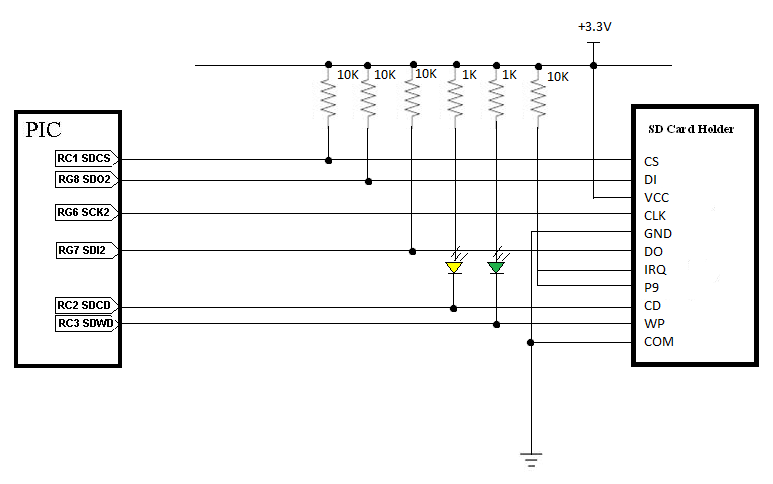
The SD card holder has 11 pins with only 6 being directly used for communication with our PIC. The SD card will be powered off 3.3V from our PIC, which will come our mini-usb connection. 10K and 1K resistors are added to allow for a voltage drop for each connection. LEDs are added for the Write Protect (WP) and Card Detect (CD) to see if the card is being read properly externally from the PIC. The LEDs turning on signifies that the card is detected and write protect is off. We did not use a resistor for the clock line. The IRQ and P9 pins on the SD card holder were not needed for SPI communication, so they were not connected to the PIC. However, they need to be powered for the SD card holder to operate properly.
| PIN Label | Function |
|---|---|
| RC1 SDCS | Digital output for SD card select |
| RG8 SDO2 | Module 2 SPI output from the PIC to the SD card |
| RG6 SCK2 | Serial Clock module 2 |
| RG7 SDI2 | Module 2 SPI input from the SD card to the PIC |
| RC2 SDCD | Digital input from SD card for card detect |
| RC3 SDWP | Digital input from SD card for write protect |
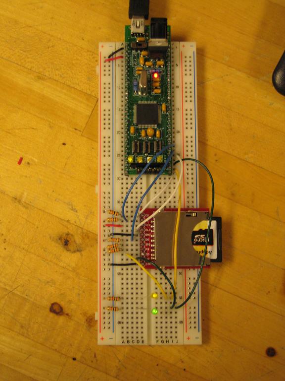
We soldered square pin headers onto the SD card holder to allow easy connection to our breadboard. Please see our circuit below for more detail.
Code
The code used for this project was based upon the companion code to the recommended text Programming 32-bit Microcontrollers in C: Exploring the PIC32 by Lucio di Jasio. The complete text in PDF form can be accessed here. The relevant sections for our project were Day 14: Mass Storage and Day 15: File I/O, which can be found on pages 403 and 427 of the text, respectively.
All the necessary companion files for Days 14 and 15 can be downloaded here. This code has been modified slightly for the purposes of our project. One major modification was the exclusion of the LCD screen and accompanying code, which was left out for the sake of simplicity. Our group focused on the Day 14 code, which can be found in the "14 SDMMC" folder. Upon opening the MPLAB Project "SDMMC," the user should see three .c files in the Source Files folder. These include Explore.c, RWTest.c, and SDMMC.c. Under the Header Files folder, should be HardwareProfile.h, HardwareProfileNU32.h, and SDMMC.h. Finally, procdefs.ld should be included under Other Files.
The complete code for RWTest.c is shown below. The rest of the files can be downloaded from the provided link.
/*
**	RWTest.c
**
*/
// configuration bit settings, Fcy=72MHz, Fpb=36MHz
#pragma config POSCMOD=XT, FNOSC=PRIPLL
#pragma config FPLLIDIV=DIV_2, FPLLMUL=MUL_18, FPLLODIV=DIV_1
#pragma config FPBDIV=DIV_2, FWDTEN=OFF, CP=OFF, BWP=OFF

#include <HardwareProfile.h>
#include <explore.h>
#include <SDMMC.h>
#include <plib.h>
#include <fileio.h>

#define START_ADDRESS       10000   // start block address
#define N_BLOCKS            10      // number of blocks
#define B_SIZE              512     // sector/data block size

char    data[ B_SIZE];
char  buffer[ B_SIZE];

main( void)
{
    SYSTEMConfigPerformance(SYS_FREQ);
    mInitAllLEDs();
    TRISCbits.TRISC1 = 0;

    LBA addr;
    int i, j, r;

    // 1. initializations
    initSD();		        // init SD/MMC module

    // 2. fill the buffer with pattern
    for( i=0; i<B_SIZE; i++)
        data[i]= i;

    // 3. wait for the card to be inserted
    while( !getCD());       // check CD switch
    Delayms( 100);          // wait contacts de-bounce
    if ( initMedia())       // init card
    {  // if error code returned
        goto End;
    }

    // 4. fill 16 groups of N_BLOCK sectors with data
    addr = START_ADDRESS;
    for( j=0; j<16; j++)
    {
        for( i=0; i<N_BLOCKS; i++)
        {
            if (!writeSECTOR( addr+i*j, data))
            {  // writing failed
                goto End;
            }
        } // i
    } // j

    // 5. verify the contents of each sector written
    addr = START_ADDRESS;
    for( j=0; j<16; j++)
    {
        for( i=0; i<N_BLOCKS; i++)
        {   // read back one block at a time
            if (!readSECTOR( addr+i*j, buffer))
            {   // reading failed
                goto End;
            }
		while(1){
			mLED_3_On();
		}
            // verify each block content
            if ( memcmp( data, buffer, B_SIZE))
            {   // mismatch
                goto End;
            }
        } // i
    } // j

    // 6. indicate successful execution

End:
    // main loop
    while( 1);

} // main
The code first includes a section for initializations including initializations for the SD card. The function initSD initializes Card Select as an output as well as setting the clock speed. The LED initialization is included only for the purposes of debugging and can be excluded if desired.
The code then waits for the SD card to be inserted before initializing the media. This function includes enabling and resetting the SD card.
Finally, the program writes blocks of data to the SD card. If successful, it will read the data back again. It is at this point that our code fails. Specifically, in the function writeSECTOR, the data is sent and then the code checks to see if the data was accepted. The data accept check is currently returning 0. This seems to suggest that the SD card is not successfully storing the data.

