PIC32MX: SPI External RAM
Original Assignment
Do not erase this section!
Your assignment is to interface to the SPI 23K256 SRAM chip.
Overview
This page will guide you how to interface the PIC32 board with the 23K256 external RAM using SPI.
Circuit
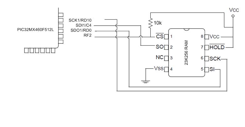
Circuit diagram showing PIC32 connected to external RAM 23K256. The circuit is an edited version of a circuit from this microchip documentation [1].

Code
1. Go to this link [2] and download "AN1277 Source Code" folder.
2. Add the PIC32 files and other requirements to your MPLAB project; instructions here [3].
3. Edit the main.c file you downloaded from step 1 to match usage for the PIC32 board. The original code is also edited make testing easier. The code here has the PIC send data to store in the external RAM, and read the data back from the external RAM. It does this for the three modes available for the 23K256 external ram chip: byte mode, page mode, and sequential mode.
#include <plib.h>
#include <string.h>
#include "HardwareProfile.h"
#include "SRAMDriver.h"

// Configuration Bit settings
// SYSCLK = 80 MHz (8MHz Crystal/ FPLLIDIV * FPLLMUL / FPLLODIV)
// PBCLK = 40 MHz
// Primary Osc w/PLL (XT+,HS+,EC+PLL)
// WDT OFF
// Other options are don't care
//
#pragma config FPLLMUL = MUL_20, FPLLIDIV = DIV_2, FPLLODIV = DIV_1, FWDTEN = OFF
#pragma config POSCMOD = HS, FNOSC = PRIPLL, FPBDIV = DIV_1

int main(void)
{

  unsigned char ReadVal,Cnt;
  unsigned char RandomSendData;
  unsigned char SRAMBufPage[SRAMPageSize];
  unsigned char SRAMBufCheckPage[SRAMPageSize];
  unsigned char SRAMBufSeq[10];
  unsigned char SRAMBufCheckSeq[10];

  // Configure the device for maximum performance but do not change the PBDIV
  // Given the options, this function will change the flash wait states, RAM
  // wait state and enable prefetch cache but will not change the PBDIV.
  // The PBDIV value is already set via the pragma FPBDIV option above..
  SYSTEMConfig(SYS_FREQ, SYS_CFG_WAIT_STATES | SYS_CFG_PCACHE);

  InitSRAM();

  while(1)
  {

  //Byte Mode
     SRAMWriteStatusReg(SRAMByteMode);

     //Write random byte to 0x0010 memory location of SRAM
     RandomSendData = rand();
     SRAMWriteByte(0x00,0x10,RandomSendData);

     //Read 0x0010 memory location of SRAM
     ReadVal = SRAMReadByte(0x00,0x10);

  //Page Mode
     SRAMWriteStatusReg(SRAMPageMode);
     memset(SRAMBufPage,0,sizeof(SRAMBufPage));   //Reset SRAMBuf location to 0x00 value
     memset(SRAMBufCheckPage,0,sizeof(SRAMBufCheckPage));   //Reset SRAMBuf location to 0x00 value

     //Write 32bytes from SRAMBuf array to first page of SRAM
     for(Cnt = 0;Cnt<32;Cnt++)
     {
        SRAMBufPage[Cnt] = (rand());
     }
     SRAMWritePage(0x00,0x20,SRAMBufPage);

     //Read 32bytes from SRAMBuf array from first page of SRAM
     SRAMReadPage(0x00,0x20,SRAMBufCheckPage);

  //Sequential Mode
     memset(SRAMBufSeq,0,sizeof(SRAMBufSeq));   //Reset SRAMBuf location to 0x00 value
     memset(SRAMBufCheckSeq,0,sizeof(SRAMBufCheckSeq));   //Reset SRAMBufCheckSeq location to 0x00 value

     //Write 10bytes from SRAMBuf to SRAM starting from 0x0010 memory location
     for(Cnt = 0;Cnt<32;Cnt++)
     {
        SRAMBufSeq[Cnt] =(rand());
     }
     SRAMWriteStatusReg(SRAMSeqMode);

     SRAMWriteSeq(0x10,0x10,SRAMBufSeq,10);

     //Read 10bytes starting from 0x1010 memory location of SRAM and store it to SRAMBuf array
     SRAMReadSeq(0x10,0x10,SRAMBufCheckSeq,10);

  }
}
4. To see that the PIC32 and the external RAM are operating correctly, you can observe the communication lines. You should be able to see data, similar to that described in this microchip documentation http://ww1.microchip.com/downloads/en/AppNotes/01277A.pdf].
5. You can also choose to view the data being sent and read through UART on the PC. You can do this by adding some code. First, configure UART2, adding this code to the start of the main loop:
  mInitAllLEDs();
  int pbClk = SYSTEMConfigPerformance(SYS_FREQ);

  #define config1    UART_EN | UART_IDLE_CON | UART_RX_TX | UART_DIS_WAKE | UART_DIS_LOOPBACK | UART_DIS_ABAUD |  UART_NO_PAR_8BIT | UART_1STOPBIT | UART_IRDA_DIS | UART_DIS_BCLK_CTS_RTS| UART_NORMAL_RX | UART_BRGH_SIXTEEN

  // define setup Configuration 2 for OpenUARTx
     // IrDA encoded UxTX idle state is '0'
     // Enable UxRX pin
     // Enable UxTX pin
     // Interrupt on transfer of every character to TSR
     // Interrupt on every char received
     // Disable 9-bit address detect
     // Rx Buffer Over run status bit clear
  #define config2      UART_TX_PIN_LOW | UART_RX_ENABLE | UART_TX_ENABLE | UART_INT_TX | UART_INT_RX_CHAR | UART_ADR_DETECT_DIS  | UART_RX_OVERRUN_CLEAR

  // Open UART2 with config1 and config2
  OpenUART2( config1, config2, pbClk/16/DESIRED_BAUDRATE-1);   // calculate actual BAUD generate value.
     //OpenUART2( UART_EN | UART_NO_PAR_8BIT | UART_1STOPBIT, UART_RX_ENABLE | UART_TX_ENABLE, (pbClk/16/DESIRED_BAUDRATE

  putsUART2("Init Done\r\n");
  //While loop to test LED functionality