Automated Fish Refuge
Team Members
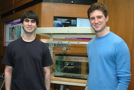
James Cooper - ME
Chris Ryan - BME
Overview
The weakly electric knifefish prefers to hide in tight spaces rather than to swim in the open. The fish will attempt to stay within an enclosure if the enclosure is moved. This provides a unique opportunity to study its behavior and the control of its unique ribbon fin locomotion. The goal of this project was to build a device that moves a box under computer control for Professor MacIver's lab. During operation, the box can oscillate back and forth in one degree of freedom. Unlike most fish, the ribbon fin allows the knifefish to move forward, backward, up, and down. Our device is manually adjustable (for reliability) so that the angle of oscillation and the angle of the enclosure can be set independently, each by steps of 10 degrees.
How To Adjust Setup
We designed this project to easily configure to the changing needs of the user. On the mechanical side, the base is made from 80/20 aluminum square (1"x1") framing that has easily adjustable connections with just an allen wrench. This allows the user to raise or lower the height of the arm and also adjust the outside legs to the length of the tank. The sliding quarter circles allow the user to adjust the location and angle of the arm(and the oscillating motion) to any direction. The arm attaches to the quarter circle by two long bolts and wing nuts that keep them in place. Similarly, the end of the arm has another quarter circle which allows for the fish enclosure to independently adjust to any angle and has similar plastic bolts and wing nuts.
The design of the program also allows for a variety of configurations for specific needs. The PIC's programming acts as simply a transfer from an array of delay times to a signal for the L297 chip. The conversion from user input to an array of delay times is done in Matlab which is a common program that is easily configurable to the user's need. As noted below, there are two main types of programs that run the device: the functions that convert user input to delay times array function and the function that sends the array to the PIC. This modularity adds another dimension of adjustability where the user can put in any function or even create their own simple Matlab function to send a specific array to the second program.
How To Control
Once you have the setup orientated in the desired position, all you need to do to start having your refuge movie is send the PIC the control commands from MATLAB. In this section, we will go over how to create the array that contains the control parameters, and then how to send it to the PIC. We separated this into two function calls to allow the user to have complete control over the original path selected, and then allow the sending function to check to make sure the path selected is valid.
Generating Path
The user has 5 different way to generate the path. We created a MATLAB function to generate a square wave, a triangle wave, and a sin wave. We also created a function that allows the user to put in a function handle, and then get out the path from that. The final option is for the user to create their own without the assistance of any of the function we wrote.
The path is an array of delay times in between steps sent to the stepper motor. The way the stepper motor work is you send a pulse to the motor every time you want it to take a step. Each step on the stepper motor is 1.8 degrees rotation. The diameter of the pulley attached to the shaft of the motor is 45.2882 mm, which means the distance per step is 0.7114 mm. The array of delay times is the amount of time in between each step in microseconds (10^-6 seconds). The sign of the delay time states which direction it is going in. Positive for forward, and negative for backward.
For the square wave generator, all you need to do is enter the forward velocity (mm/s), the backward velocity (mm/s), and how far it travels (mm). The square wave generator will first have the refuge go forward, before it goes backward.
   [time_array]=square_to_delay(vel1,vel2,length)
   time_array is the outputted array of delay times
   vel1 is forward velocity (mm/s)
   vel2 is backward velocity (mm/s)
   length is length traveled (mm)
For the triangle wave generator, all you need to do is enter the peak forward velocity (mm/s), the peak backward velocity (mm/s), and how far it travels (mm). The triangle wave generator will first have the refuge go forward, before it goes backward.
   [time_array]=triangle_to_delay(vmax1,vmax2,length)
   time_array is the outputted array of delay times
   vmax1 is forward peak velocity (mm/s)
   vmax2 is backward peak velocity (mm/s)
   length is length traveled (mm)
Sending Path
Electrical Design
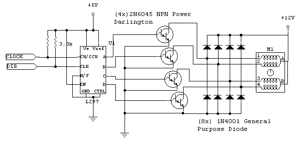
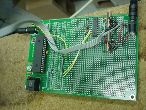
The circuit design and building is minimal for this project. The only necessary circuitry is to connect the unipolar stepper motor with the pic, and connect the RS232 cable to the pic. Please see the pages for the Unipolar Stepper Motor Driver Circuit and the PIC RS232 cable for more information on how they work and how to set them up.
   Pin D0 is connected to Clock
   Pin D1 is connected to DIR
RS232 Cable Connections
   Orange Wire to RC6
   Ground to Ground
Overall Circuit
[[Media:fish stuff ]]== Mechanical Design ==


