4520 Board use
Using the 4520 board
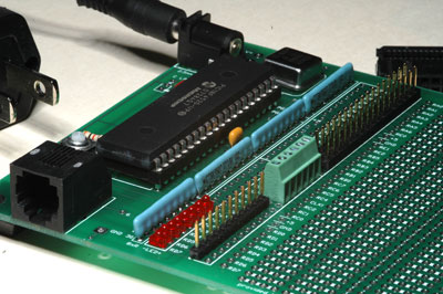
The 4520 board is intended to allow several kinds of connectors on 0.1" centers. Shown at right are a single-line header, which, if mounted underside could be plugged into a solderless breadboard. You also see a terminal strip for attaching wires, and a double-row header that mates to a ribbon cable connector, which could efficiently bring many PIC pins to another board. Ribbon cable connectors up to 50-wide are available.
Larger picture of the whole board
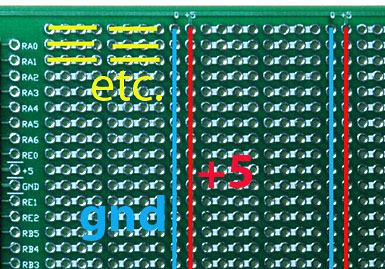
The +5 and Ground of the PIC, from the barrel connector and off-board power supply (and regulator if installed), are brought to common "rails" as shown in red and blue here.
Larger picture of whole board.
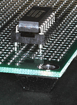
The rest of the connection points are connected only in groups of 4. It's intended that chip sockets span between two groups of 4, across the +5 and ground rails. Whenever possible socket your components.
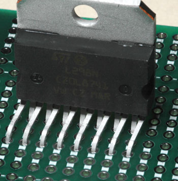
We don't have sockets for the popular L298N H-bridges. They can be soldered between adjacent groups of 4, by displacing one row of leads 0.05".


