PIC MCUs: Hardware and Connections
Required Hardware
In order to program and debug a PIC microcontroller, you will need a few pieces of hardware.
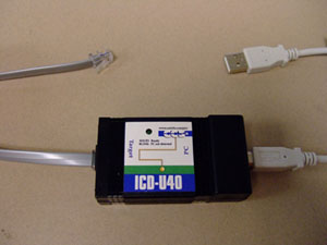
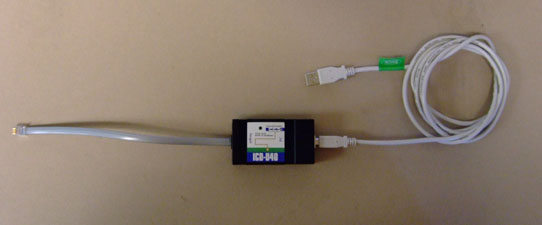
ICD-U40
The ICD-U40 is an In-Circuit-Debugger/Programmer that allows the user, through CCS C Windows IDE, to program and interactively debug a PIC microcontroller.


Hardware Connection
USB to ICD-U40
The first time the ICD-U40 is connected to a computer via a USB cable, a driver for the ICD-U40 needs to be installed. This can be done either directly off of the installation disk that came with the CCS C Windows IDE, or off of the CCS Inc. website: http://www.ccsinfo.com/content.php?page=ICD
ICD-U40 to PIC MCU
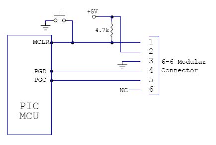
The ICD-U40 programmer/debugger connects to the PIC microcontroller through a six wire modular cable. Although the boards provided for ME 233/333/433 and in the lab are already wired correctly, a wiring diagram for communication with the PIC microcontroller is given below for reference.

While the ICD is connected to the PIC MCU and to your computer via a USB cable the Windows IDE will be able to communicate with the PIC microcontroller. In order to program or debug successfully, these connections must be made correctly.