PIC MCUs: Hardware and Connections
Required Hardware
In order to program and debug a PIC microcontroller, you will need a few pieces of hardware.
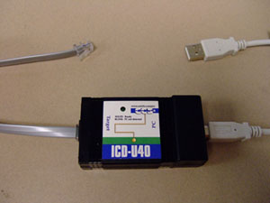
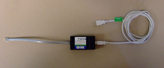
ICD-U40
The ICD-U40 is an In-Circuit-Debugger/Programmer that allows the user, through CCS C Windows IDE, to program and interactively debug a PIC microcontroller.
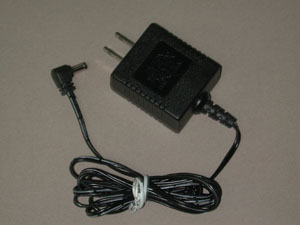
5V DC Power Supply
Although the 4520 board has a voltage regulator that is capable of handling larger voltages (up tp 30 volts), a five volt power supply should be used if available to avoid needing a heat sink for the regulator.
Hardware Connection
USB to ICD-U40
The first time the ICD-U40 is connected to a computer via a USB cable, a driver for the ICD-U40 needs to be installed. This can be done either directly off of the installation disk that came with the CCS C Windows IDE, or off of the CCS Inc. website: http://www.ccsinfo.com/content.php?page=ICD
ICD-U40 to PIC MCU
The ICD-U40 programmer/debugger connects to the PIC microcontroller through a six wire modular cable. Although the boards provided for ME 233/333/433 and in the lab are already wired correctly, a wiring diagram for communication with the PIC microcontroller is given below for reference.
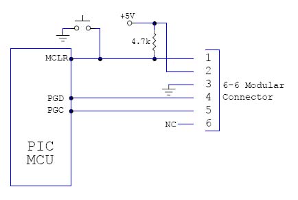
While the ICD is connected to the PIC MCU and to your computer via a USB cable the Windows IDE will be able to communicate with the PIC microcontroller. In order to program or debug successfully, these connections must be made correctly. Once all connections are made successfully the LED on the ICD-U40 will turn on.
PIC MCU Power
In order for all hardware conections to be successful, the PIC microcontroller unit itself must be powered. To do this, simply connect the pins of the MCU to power/ground as shown on the devices datasheet, or if you are using the 4520 board plug the five volt power supply into the barrel connector on the board. Also, ensure that all connections between the MCU and the ICD are made correctly as in the diagram above.
Testing Hardware Connections
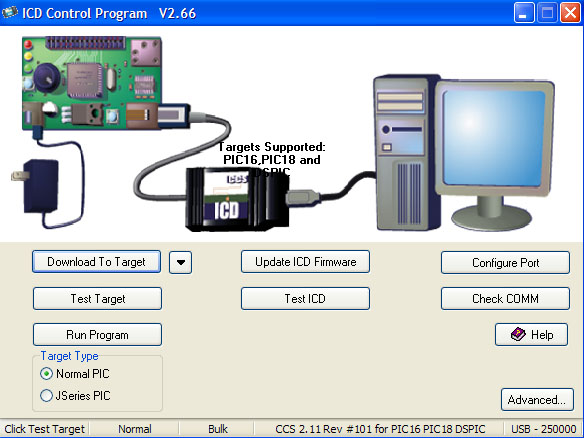
All hardware connections can be tested once all components are connected. Select Start>Programs>PIC-C>ICD to open the ICD control program (shown below). Click through "Test Target", "Test ICD", and "Check COMM". The hardware is connected properly if all tests are passed.
