PIC18F4520: PWM Motor Control
Pulse Width Modulation, or PWM, is a technique used to vary the average magnitude of a signal by changing its duty cycle (the proportion of time that a signal is active or "high"). For a more in-depth introduction to PWM motor control click here.
Available Pins
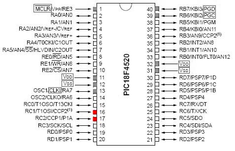
The PIC18F4520 is capable of outputing a PWM signal on two separate channels: CCP1 and CCP2 (shown below). The red pins have the capability of outputing PWM, while the grey are usually committed to communication or power.
Unidirectional Motor Control
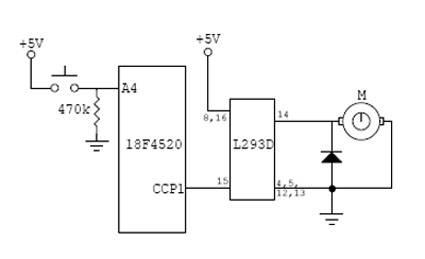
This section will detail how to set up a simple program and circuit to control a motor using a PIC microcontroller and PWM.
Sample Code
Program to run a motor at different speeds using pulse width modulation (PWM), controlled by a push button.
First include header file with definitions for specific PIC. Set fuses. HS is type of external clock, low voltage protection (LVP) is off, and the watchdog timer (WDT) is off. External clock frequency of 20 MHz is specified.
  #include <18F4520.h>
  #fuses HS,NOWDT,NOPROTECT,NOLVP
  #use delay(clock=20000000)
Define pin names to be used in the main program. See header file for currently defined pin names.
#define BUTTON PIN_A4
Begin main body of program.
void main() {
Setup the CCP1 pin (PIN_C2 on the 18F4520 chip) to be a PWM output. Also set the timer to be used for PWM.
     setup_ccp1(CCP_PWM);
     setup_timer_2(T2_DIV_BY_1, 255, 1);
Setup an infinite loop, using a while statement.
while( TRUE ) {
Check whether button is pressed or not, and vary duty cycle of PWM accordingly. Note that duty cycle is defined from 0-255 with 0 being 0% and 255 being 100% (8-bit number).
        if (input(BUTTON)){
           set_pwm1_duty(235);}
        else {
           set_pwm1_duty(135);}
    }
  }
Circuit Diagram
Bidirectional Motor Control
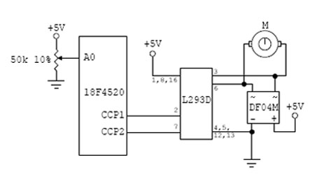
This section will detail how to set up bidirectional motor control using a PIC microcontroller and PWM.
Sample Code
Program to run a motor bidirectionally at varying speeds depending on the position of a potentiometer.
First include header file with definitions for specific PIC. Set fuses. HS is type of external clock, low voltage protection (LVP) is off, and the watchdog timer (WDT) is off. External clock frequency of 20 MHz is specified.
  #include <18F4520.h>
  #fuses HS,NOWDT,NOPROTECT,NOLVP
  #use delay(clock=20000000)
Introduce the variables to be used in the main program.
  int read;
  int readlow;
  int readhigh;
Begin main body of program.
void main() {
Setup the CCP1 and CCP2 to be PWM outputs. Also set the timer to be used for PWM.
     setup_ccp1(CCP_PWM);
     setup_ccp2(CCP_PWM);
     setup_timer_2(T2_DIV_BY_1, 255, 1);
Setup analog input, and which analog channel is active.
     setup_adc_ports(AN0_ANALOG);
     setup_adc(ADC_CLOCK_INTERNAL);
     set_adc_channel(0);
Setup an infinite loop, using a while statement.
while(TRUE) {
Read the analog input and define "readhigh" and "readlow" as functions of "read". Note that the value of "readhigh" varies from 0 to 255 when the potentiometer is between 140 and 255, and "readlow" behaves similarly.
        read = read_adc();
        readlow = (120-read)*2.125;
        readhigh = (read-140)*2.217;
Check the value of "read", and set the duty cycle of each PWM output signal accordingly. The H-bridge circuit used requires two inputs (the two PWM outputs of the 18F4520) to control the direction and speed of the driven motor.
        if (read<120){
           set_pwm1_duty(readlow);
           set_pwm2_duty(0);}
        else if (read>140){
           set_pwm1_duty(0);
           set_pwm2_duty(readhigh);}
        else {
           set_pwm1_duty(0);
           set_pwm2_duty(0);}
    }
  }


