Using CircuitMaker
CircuitMaker is a program that can be used to simulate circuits on a computer. The following tutorials explain some of Circuitmaker's basic functions.
Drawing Schematics
For the first part, we will create a simple voltage divider circuit.
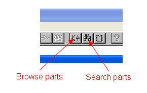
Start CircuitMaker. It should open up with a blank canvas. To add components you can either browse through CircuitMaker's catalogue, or search the the part's name, number, or description. The buttons for these tasks are found at the toolbar at the top:
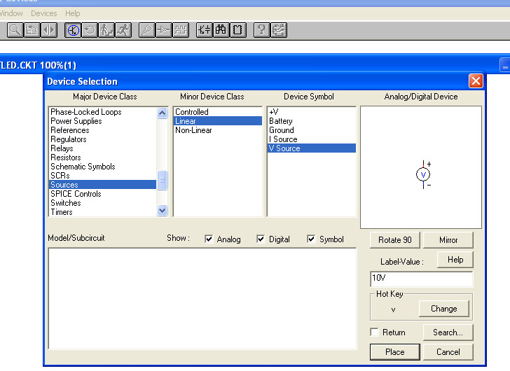
Click on the button on the left to open up the Device Selection window. The components are organized in a hiearchy:
Major Device Class > Minor Device Class > Device Symbol.
We now add a voltage source to our circuit: Source > Linear > VSource. Note that you can specify values and hot keys in this window. Checking the return box will cause this part selection window to automatically re-open after you've placed the part on the canvas.
Enter 10V into the Label-Value field and click Place. The window should disappear and your mouse cursor should become the voltage source symbol. To rotate the part, right-click. To cancel the part placement and get your mouse cursor back, press Esc on your keyboard. After you've placed the component, you can right-click it to edit its attributes. (Note that right-clicking on the empty canvas will also bring up a useful context menu.)
Now, we are going to change the voltage source from 10V to 5V. Double-click on the symbol (or right-click > Edit Device Data...) to open up a new menu. In the Label-Value field, change 10V to 5V.
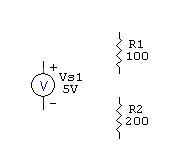
To add a resistor to our circuit, open up the device selection window again, and select Resistors > Resistors > Resistor. Enter 100 for its value.
Add a second resistors, and give it a value of 200 (Ohms).
Our circuit should look like this:
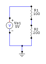
To connet our circuit, use the wire tool ![]() to connect the pins. We also must add a ground (Source > Linear > Ground in device selection window), so CircuitMaker will know what to use as a reference when calculating voltages. Hook up the circuit like this:
to connect the pins. We also must add a ground (Source > Linear > Ground in device selection window), so CircuitMaker will know what to use as a reference when calculating voltages. Hook up the circuit like this:
To simulate the circuit, click the run button ![]()


