Passive Filters
RL Circuits
Charging
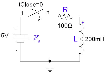
If the inductor is initially uncharged and we want to charge it by inserting a voltage source in the RL circuit:
The inductor initially has a very high resistance, as energy is going into building up a magnetic field. Once the magnetic field is up and no longer changing, the inductor will act like a short circuit. The current at steady state will be equal to . Since the inductor is acting like a short circuit at steady state, the voltage across the inductor then will be 0. The current through the inductor is given by:
Discharging
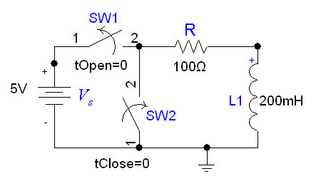
In the following circuit, the inductor initially has current flowing through it; we replace the voltage source with a short circuit at .
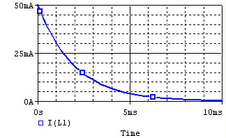
After we cut out the voltage source, the voltage across the inductor will be , but the higher voltage will be at the negative terminal of the inductor. Thus, . The the current flowing through the inductor at time t is given by:
where .
The time constant for the RL circuit is equal to .
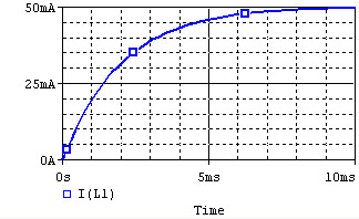
The voltage and current of the inductor for the circuits above are given by the graphs below, from t=0 to t=5L/R. The voltage is measured at the "+" terminal of the inductor, relative to the ground. A positive current flows into the inductor from this terminal; a negative current flows out of this terminal.:
| Voltage | Current | |
|---|---|---|
| Charge | 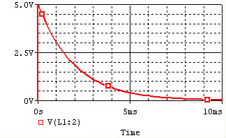 |
|
| Discharge | 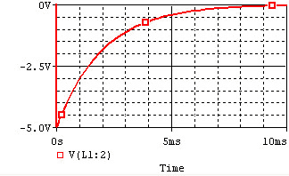 |
|
Remember that for an inductor, . Note that the voltage across the inductor can change instantly at t=0, but the current changes slowly.

