Difference between revisions of "Machine Vision Localization System"
| Line 1: | Line 1: | ||
__TOC__ |
__TOC__ |
||
=Project Files= |
=Project Files= |
||
*[[Image: |
*[[Image:vision_system_localization_project.zip]] (Project files with source code) |
||
*[[Image:vision_localization.zip]] (executable only) |
*[[Image:vision_localization.zip]] (executable only) |
||
Revision as of 13:38, 21 January 2009
Project Files
- File:Vision system localization project.zip (Project files with source code)
- File:Vision localization.zip (executable only)
Overview
This is a machine vision system that tracks multiple targets and can send out the positions via the serial port. It was developed specifically for the Swarm Robotics project, but can be adapted for other uses. It is based upon the Indoor_Localization_System, but has several enhancements and bug fixes. Refer to Indoor_Localization_System for a basic overview of the setup of the system and the workings of the patter identification algorithm.
Major Enhancements/Changes
- The system will now mark the targets with an overlay and display coordinate data onscreen.
- The serial output is now formatted for the XBee radio using the XBee's API mode with escape characters.
- The calibration routine has been improved, and only needs to be performed once.
- A command interface for sending out commands via the serial port has been added.
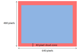
- The system will discard targets too close to the edge of the camera frame to prevent misidentification due to clipping.
- The origin of the world coordinate is now in the middle, not the lower left corner.
- The GUI displaying the camera frames is now full sized instead of a thumbnail. However, if your monitor isn't big enough, you can resize them.
Major Bug Fixes
- Two major memory leaks fixed.
- Calibration matricies are now calculated correctly.
- File handling bug that causes an off-by-one error in LoadTargetData() fixed.
Target Patterns
The target patterns and preprocessor can be downloaded at Indoor_Localization_System#Pre-processing_program_source_with_final_patterns:.
OpenCV Documentation
Operation
Setting up the Cameras
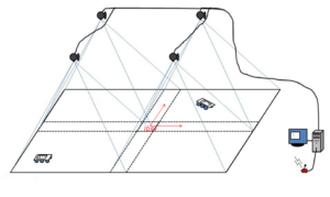
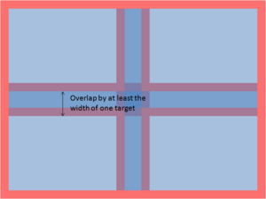
The cameras should be set up according to Indoor_Localization_System with one caveat: targets at the edge of the camera frame will now be discarded. This prevents misidentification of patterns if one or more dots in the pattern fall off the screen, but it also means that there must be enough overlap that when the target is in the dead-zone of one camera, it is picked up by another camera.
The height of the cameras will determine how small your patterns can be before becoming indistinguishable. Changing the height also changes the focus, so be sure to adjust the focus when the height is changed.
How to Use The System
Camera Setup
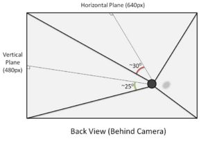
The four cameras used were standard Logitech QuickCam Communicate Deluxes. For future use, the videoInput library used is very compatible and works with most capture devices. As measured, the viewing angle (from center) of the Logitech cameras was around 30 degrees (horizontal plane) and 25 degrees (vertical plane).
Before attaching the cameras, several considerations must be made.
1. Choose a desired ALL WHITE area to cover. ***IMPORTANT: If you want to be able to cover an continuous region, the images as seen by the cameras must overlap to ensure a target is at least fully visible in one frame of a camera*** Keep in mind that there is a trade-off between area, and resolution. In addition, the size of the patterns will have to be increased above the threshold of noise.
2. Ensure that the cameras are all facing the same direction. As viewed from above, the "top" of the cameras should all be facing the same direction (N/S/E/W). For future use, if these directions must be variable, the image reflection and rotation parameters can be adjusted in software (though this has not been implemented).
3. Try to mount the cameras as "normal" as possible. Although the camera calibration should determine the correct pose information, keeping the lenses of the cameras as normal as possible will reduce the amount of noise at the edges of the images.
Computer Setup
In the current implementation, this system has been developed for a Windows based computer (as restricted by the videoInput library). The system should run in Windows XP or Vista. To setup the computer to develop and run the software, the three required libraries must be installed.
1. Download and install the Logitech QuickCam Deluxe Webcam Drivers - http://www.logitech.com/index.cfm/435/3057&cl=us,en
2. Download and install Microsoft Visual Studio Express - http://www.microsoft.com/express/default.aspx
3. Download and install Microsoft Windows Platform SDK - http://www.microsoft.com/downloads/details.aspx?FamilyId=0BAF2B35-C656-4969-ACE8-E4C0C0716ADB&displaylang=en
4. Download and install Microsoft DirectX 9+ SDK - http://www.microsoft.com/downloads/details.aspx?FamilyId=572BE8A6-263A-4424-A7FE-69CFF1A5B180&displaylang=en
5. Download and install Intel OpenCV Library - http://sourceforge.net/projects/opencvlibrary/
6. Download and install the videoInput Library - http://muonics.net/school/spring05/videoInput/
7. Download the source code for the vision system here: Media: Vision_localization_system_project.zip
The project will probably not compile right after you open it. You will have to put the correct directories into the environment. In Visual C++, go to
Tools>Options>Project and Solutions>VC++ directories
and select Include files in the drop-down menu. Add (the directory paths on your computer may be different depending on your system, and the versions you installed.):
- C:\Program Files\OpenCV\otherlibs\highgui
- C:\Program Files\OpenCV\otherlibs\cvcam\include
- C:\Program Files\OpenCV\cvaux\include
- C:\Program Files\OpenCV\cxcore\include
- C:\Program Files\OpenCV\cv\include
- C:\Program Files\Microsoft SDKs\Windows\v6.1\Include
select Library files from the drop-down menu and add:
- C:\Program Files\Microsoft SDKs\Windows\v6.1\Lib
- C:\Users\LIMS\Documents\Visual Studio 2005\Libraries\videoInput0.1991\videoInputSrcAndDemos\libs\DShow\lib
- C:\Users\LIMS\Documents\Visual Studio 2005\Libraries\videoInput0.1991\compiledLib\compiledByVS2005
- C:\Users\LIMS\Documents\Visual Studio 2005\Libraries\videoInput0.1991\videoInputSrcAndDemos\libs\videoInput
Starting the Program
- Compile and run the program.
- When you first run the program, it will open up a console window and ask you to enter a COM port number. This is the number of the serial port that will be used to send out data. Enter the number, and press Enter. (e.g. Enter COM number: 4<enter>)
- The program should now connect to the cameras, and will open two new windows: one with numbered quadrants (the GUI window), and one displaying the view of one of the cameras. Use you mouse to click on the quadrant that corresponds to the camera view. Repeat until all four cameras have been matched to the quadrants.
- Make sure the GUI window is selected, and press Enter.
- Go back to the console window, and you should now see a message asking you if you want to recalibrate your cameras. Press y for yes and n for no, then press Enter. To recalibrate your cameras, see the calibration section.
- The GUI window should now show a thresholded image, and the console will display how many dots the camera sees. Adjust the thresholding parameters (+ and - for black/white, z and x for area) until you are satisfied with the thresholded image.
- Make sure the GUI window is selected, then hit Enter.
- Remove any calibration patterns, and hit Enter. The program should now be running.
- When you turn on the robots, they will be in sleep mode. Use the wake command to start them.
Camera Calibration
The camera calibration routine used is explained in the document Image_Formation_and Camera_Calibration.pdf by Professor Ying Wu.
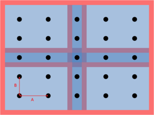
The calibration routine uses 9 equally-spaced points per camera to find a mapping from the image coordinates to the real-world coordinates. The field of view of the four cameras must overlap the center horizontal and vertical dots that form a '+' shape.
The size of the dots is not very important; the center of mass of each of the dots will be used.
To calibrate:
- Place the 25 equally spaced dots on the testbed. The dots should be well distributed throughout the testbed (don't bunch the dots all up in a small area).
- Start the program, and type in 'y' at the prompt that asks whether or not you wish to calibrate.
- Enter the horizontal spacing (parameter A in the diagram) and vertical spacing (parameter B in the diagram) when prompted. These numbers are recorded in the file calibration_dot_spacing.txt.
- The GUI window will then display a thresholded image and the console will display the number of dots seen by each camera. Adjust the thresholding values until each camera sees only the nine dots being used to calibrate the camera.
- Select the GUI window and hit Enter.
- Remove the dots.
- Select the GUI window and hit Enter.
The program should now be running. Your calibration information will be recorded in Quadrant0.txt, Quadrant1.txt, Quadrant2.txt, Quadrant3.txt, and calibration_dot_spacing.txt. If you choose not to recalibrate your cameras next time, the data in these files will be used to generate the calibration matrices.
When calibrating, the dots should be raised to the same height as the patterns on the robots. It is possible to calibrate one camera at a time using only 9 dots by placing the dots under one camera at a time and running the calibration routine four times, making a copy of the Quadrant_.txt file generated by the calibration routine for that camera (the other three files will be garbage) each time so that it will not be overwritten. You can then copy the four good files back into the directory.
Pausing
Hit 'p' to pause the program, and hit 'p' again to resume.
Using the Command Console
To enter the command mode, hit 'c'. When in the command mode, the main loop is not running; the command mode must be exited to resume. Type 'exit' to exit the command mode and resume the main loop.
Note: There is no guarantee that all of the robots will receive the command, due to packet loss. It is advisable to send the command out multiple times to make sure the robots all receive it. You can use the arrow keys to find previously sent messages.
Enter commands in the following syntax:
<command name> <target ID> <parameter 1> <parameter 2> ... <parameter N>
To broadcast the message, use ID 0.
You can also enter multiple commands at a time:
sleep 1 sleep 2 wake 4 goto 0 100 -100 deadb 0 150
Commands
| Command | Description | Parameters | Example |
|---|---|---|---|
| sleep | The robot will stop moving and stop sending data. | sleep <ID> | sleep 0 |
| wake | The robot will wake from sleep and resume moving and sending data | wake <ID> | wake 0 |
| goal | Change the swarm's goal state. | goal <ID> <Ix> <Iy> <Ixx> <Ixy> <Iyy> | goal 0 100 300 160000 40000 40000 |
| goto | Similar to goal, but only changes <Ix> and <Iy>. | goto <ID> <Ix> <Iy> | goto 0 100 300 |
| deadb | Change the robot motor deadband. The motors will only move for speeds (wheel ticks per second) faster than this. This removes some jittering at low speeds. |
deadb <ID> <velocity> | deadb 0 150 |
| egain | Change the estimator gains. | egain <ID> <KP> <KI> <Gamma> | egain 0 0.7 0.1 0.05 |
| cgain | Change the motion controller gains. | cgain <ID> <KIx> <KIy> <KIxx> <KIxy> <KIyy> | cgain 0 2 2 0.001 0.001 0.001 |
| commr | Change the communication radius distance. The agent will discard any packets from other agents further away than this distance. |
commr <ID> <distance> | commr 0 1500 |
| speed | Change the maximum allowed speed for the robot. | speed <ID> <speed> | speed 0 300 |
| safed | Change the obstacle avoidance threshold. | speed <ID> <distance> | safed 0 200 |
Exiting the Program
Press ESC to quit the program.
