Difference between revisions of "Indoor Localization System"
ScottMcLeod (talk | contribs) |
ScottMcLeod (talk | contribs) |
||
| Line 9: | Line 9: | ||
This system uses four standard webcams to locate known patterns in a real time image, and transmit positioning information over a serial interface. This serial interface is most often connected to a wireless Zigbee® module. The cameras are mounted in fixed positions above the target area. The height of the cameras can be adjusted to increase either the positioning resolution or the area of the world frame. These constraints are a function of the field of view of the lenses. Below is a diagram illustrating this system’s basic setup. |
This system uses four standard webcams to locate known patterns in a real time image, and transmit positioning information over a serial interface. This serial interface is most often connected to a wireless Zigbee® module. The cameras are mounted in fixed positions above the target area. The height of the cameras can be adjusted to increase either the positioning resolution or the area of the world frame. These constraints are a function of the field of view of the lenses. Below is a diagram illustrating this system’s basic setup. |
||
[[Image:visual_localization_system.jpg|center|Overview of System]] |
[[Image:visual_localization_system.jpg|center|thumb|600px|Overview of System]] |
||
Here, we can see the four cameras are mounted rigidly above the world frame. Note that the cameras actual placement must have an overlap along inside edges at least the size of one target. This is necessary to ensure any given target is at least fully inside one camera’s frame. |
Here, we can see the four cameras are mounted rigidly above the world frame. Note that the cameras actual placement must have an overlap along inside edges at least the size of one target. This is necessary to ensure any given target is at least fully inside one camera’s frame. |
||
Revision as of 12:55, 19 March 2008
Motivation
For relatively simple autonomous robots, knowing an absolute position in the world frame is a very complex challenge. Many systems attempt to approximate this positioning information using relative measurements from encoders, or local landmarks. Opposed to an absolute system, these relativistic designs are subject to cumulating errors. In this design, the positioning information is calculated by an external computer which then transmits data over a wireless module.
This system can be envisioned as an indoor GPS, where positioning information of known patterns is transmitted over a wireless module available for anyone to read. Unlike a GPS, this vision system has much higher resolution and is designed for indoor use.
Overview of Design
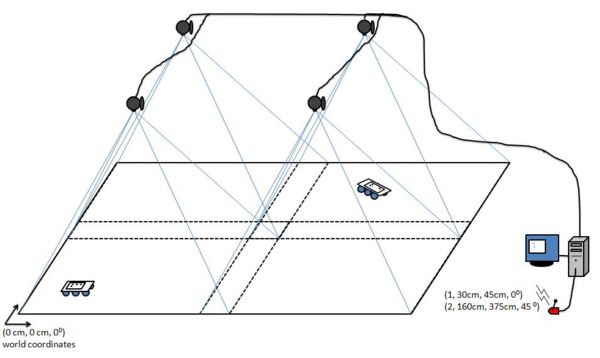
This system uses four standard webcams to locate known patterns in a real time image, and transmit positioning information over a serial interface. This serial interface is most often connected to a wireless Zigbee® module. The cameras are mounted in fixed positions above the target area. The height of the cameras can be adjusted to increase either the positioning resolution or the area of the world frame. These constraints are a function of the field of view of the lenses. Below is a diagram illustrating this system’s basic setup.
Here, we can see the four cameras are mounted rigidly above the world frame. Note that the cameras actual placement must have an overlap along inside edges at least the size of one target. This is necessary to ensure any given target is at least fully inside one camera’s frame.
Goals
• To provide real-time (X, Y, θ) position information to an arbitrary number of targets (<20) in a fixed world frame using a home-made computer vision system.
• Maximize throughput and accuracy
• Minimize latency and noise
• Easy re-calibration of camera poses.
• Reduced cost (as compared to real-time operating systems and frame grabbing technology)
Tools Used
Software
• IDE: Microsoft Visual C++ Express Edition – freeware (http://www.microsoft.com/express/default.aspx)
• Vision Library: Intel OpenCV – open source c++ (http://sourceforge.net/projects/opencvlibrary/)
• Camera Capture Library: VideoInput – open source c++ (http://muonics.net/school/spring05/videoInput/)
Hardware
• Four Logitech QuickCam Communicate Deluxe USB2.0 webcams
• One 4-port USB2.0 Hub
• Computer to run algorithm
Algorithm Design
Overview
To identify different objects and transmit position and rotation information a 3x3 pattern of black circles is used. To create both position and orientation, the patterns must have at least 3 dots in a rotationally invariant configuration.
Pre-Processing
Target Classification
Before the system is executed in real time, two tasks must be completed. The first is pre-processing the possible targets to match (the patterns of 3x3 dots). This is done by first creating a subset of targets from the master template. Each target must be invariant in rotation, reflection, scale and translation. A set of targets has been included in the final project, with sample patterns. When the program is executed in real time, it will only identify targets from the trained subset of patterns.
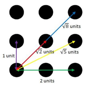
When the targets are pre-processed, unique information is recorded to identify each pattern. In particular, the algorithm counts the number of dots and the relative spacing between each dot. In this sense, the pattern is identified as a unique number (corresponding to the order of target patterns in the image directory), the number of dots in the pattern, and the normalized spacing between each dot. Since the pattern is a fixed 3x3 grid, the only possible spacing between dots is 1, √2, 2, √5, or √8 units.
The last piece of information recorded is the orientation of the target. Below is a picture of this configuration. *Note to change the target, various dots are removed.
Camera Calibration
The second required step before the system can be used is training the cameras both their intrinsic parameters (focal length, geometric distortions, pixel to plane transformation) and their extrinsic pose parameters (rotation and translation of origins). In other words, the pixels in the image must be correlated to the world frame in centimeters or inches. This step is performed by using a simple linear least squares best fit model. The calibration process needs at least 6 points as measured in the world and image frames to compute a 3x4 projection matrix. In practice, we use more than these 6 points to add redundancy and help best compute an accurate projection matrix. The method used is outlined in Multiple View Geometry in Computer Vision by Richard Harley and Andrew Zisserman.

