Difference between revisions of "Robot Snake"
ClaraSmart (talk | contribs) |
ClaraSmart (talk | contribs) |
||
| Line 79: | Line 79: | ||
== Mechanical Design == |
== Mechanical Design == |
||
| ⚫ | |||
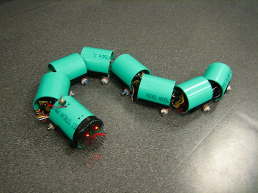
The robotic snake consists of a head segment, which houses the onboard electronics, including the xBee radio, and independently controlled body segments, which house servo motors and the batteries required to power each motor. As the snake is designed to be modular, there is no limit to the number of body segments. More segments will allow it to move more smoothly, while fewer segments will be easier to control. For this design, seven body segments were used do to material limitations. |
The robotic snake consists of a head segment, which houses the onboard electronics, including the xBee radio, and independently controlled body segments, which house servo motors and the batteries required to power each motor. As the snake is designed to be modular, there is no limit to the number of body segments. More segments will allow it to move more smoothly, while fewer segments will be easier to control. For this design, seven body segments were used do to material limitations. |
||
| Line 96: | Line 95: | ||
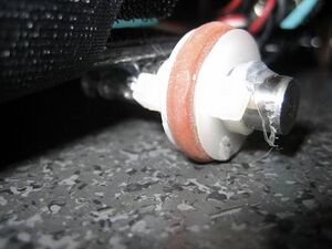
[[image:Wheel.jpg|thumb|left|A Passive Wheel on the Dowel Pin]] |
[[image:Wheel.jpg|thumb|left|A Passive Wheel on the Dowel Pin]] |
||
| ⚫ | |||
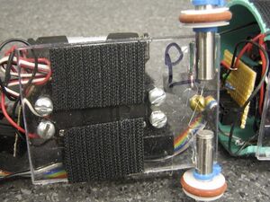
Passive wheels are mounted to the bottom of the chassis. The wheels which were used are actually 3/4 inch pulleys with o-rings around them to create friction when pushed perpendicular to the direction of motion. They have been set on polished metal dowel pins which produce very little friction, allowing the wheels to move freely. This is important as the segments must apply enough weight to create friction, but the wheels must still be able to roll. The dowel pin axles are then mounted (hot glue works but is not very strong) in the center of the chassis, the wheel is slid on and either snap rings or zip ties are used to keep it in place. Note, the center of the chassis is not the center of the polycarbonate rectangle, rather the entire chassis length includes the cantilever beam, therefore, the wheels are placed twards the back of the polycarbonate rectangle. (See Image) |
Passive wheels are mounted to the bottom of the chassis. The wheels which were used are actually 3/4 inch pulleys with o-rings around them to create friction when pushed perpendicular to the direction of motion. They have been set on polished metal dowel pins which produce very little friction, allowing the wheels to move freely. This is important as the segments must apply enough weight to create friction, but the wheels must still be able to roll. The dowel pin axles are then mounted (hot glue works but is not very strong) in the center of the chassis, the wheel is slid on and either snap rings or zip ties are used to keep it in place. Note, the center of the chassis is not the center of the polycarbonate rectangle, rather the entire chassis length includes the cantilever beam, therefore, the wheels are placed twards the back of the polycarbonate rectangle. (See Image) |
||
[[image:ChasisUnderside.jpg|thumb|left|The Underside of a Chassis]] |
|||
[[image:BuiltChasis.jpg|thumb|right|A Chasis Built Showing a Standoff and Batteries]] |
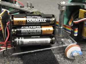
[[image:BuiltChasis.jpg|thumb|right|A Chasis Built Showing a Standoff and Batteries]] |
||
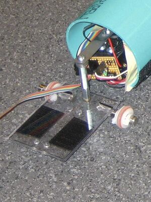
A fully assembled chassis has a mounted servo and is connected to a segment on either side. Additionally AAA batteries packs are attached to the sides of the motor with velcor, and the small electronic circuit board is mounted on the front of the motor. (See Electronic Design for more information on the circuit board and batteries. |
A fully assembled chassis has a mounted servo and is connected to a segment on either side. Additionally AAA batteries packs are attached to the sides of the motor with velcor, and the small electronic circuit board is mounted on the front of the motor. (See Electronic Design for more information on the circuit board and batteries. |
||
[[image:BallCaster.jpg|thumb| |
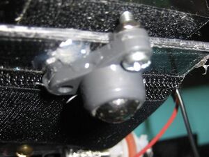
[[image:BallCaster.jpg|thumb|left|The Ball Caster Under the Front Segment]] |
||
The head segment is similar to the body segments except that no servo is mounted in the head and it is slightly longer, long enough for the PCB board which holds the PIC. However, it is still the same width as the body segments. A ball caster added to the very front will help support the extra length and help the wheels stay on the ground. |
The head segment is similar to the body segments except that no servo is mounted in the head and it is slightly longer, long enough for the PCB board which holds the PIC. However, it is still the same width as the body segments. A ball caster added to the very front will help support the extra length and help the wheels stay on the ground. |
||
[[image:Housing.jpg|thumb|right|One Segment of the Housing]] |
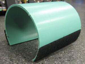
[[image:Housing.jpg|thumb|right|One Segment of the Housing]] |
||
Revision as of 23:22, 15 March 2008
Overview
Team Members
- Michael Hwang - Electrical Engineer - Class 2008
- Andrew Long - Mechanical Engineer - Class 2009
- Clara Smart - Electrical Engineer - Class 2009
Snake Motion
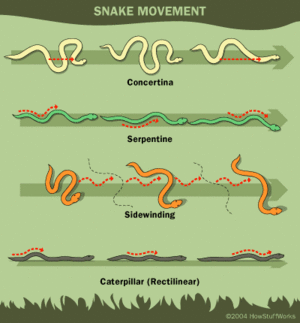
Snakes are able to adapt their movement to various environments. For instance, snakes can move across extreme environments such as sand, mud and water. Research has discovered there are four types of snake motion, as shown in the image. These motions include; serpentine movement, rectilinear movement, concertina movement and side-winding movement.<ref>Ma, Shugen. "Analysis of creeping locomotion of a snake-like robot." Advanced Robotics Vol.15, No.2 (2001): 205</ref> The most common motion exhibited by most snakes is serpentine motion where section follows a similar path. In order for snakes to successfully locomote using serpentine motion, the belly of the snake must have anisotropic coefficient of friction for the normal and tangential directions. Specifically, the normal friction must be greater than the tangential friction. As a result, when the snake exhibits a force on the ground, it will move in the tangential direction without slipping in the normal direction.<ref>Saito, Fukaya, Iwasaki. "Serpentine Locomotion with Robotic Snakes". IEEE Control Systems Magazine (Feb 2002): 66.<ref/>
Advantages / Disadvantages of Robotic Snake Motion
Advantages
Many robots are limited by the use of motorized wheels. However, there are many advantages for building a robot that mimics the motion of a snake. Several advantages for movement of snake robot are listed below:
- Move across uneven terrain since it is not dependent on wheels
- Possibly swim if water-proofed
- Move across soft ground such as sand since it can distribute its weight across wider area
Also, from a systems standpoint, the snake robot can be very modular with many redundant segments. As a result, it is very easy to replace broken segments as well as shorten or lengthen the robot.
Disadvantages
Although there are many advantages for building a snake like robot, there are several disadvantages which are listed below:
- Low power and movement efficiency
- High cost of actuators (servos or motors)
- Difficult to control high number of degrees of freedom
Cite = Page 206
Robot Snake Motion
Real snake motion does not follow specified equations. However, research has proven that the serpentine motion of a snake can be modeled with the following equations:
where the parameters a, b, and c determine the shape of the serpentine motion. The graph shows how the parameters influence the serpentine curve. Basically, a changes the appearance of the curve, b changes the number of phases, and c changes the direction.
The serpentine curve can be modeled with a snake like robot by changing the relative angles between the snake robot segments using the following formula with the number of segments (n):
where α , β , and γ are parameters used to characterize the serpentine curve and are dependent on a, b, and c as shown below:
The equations above for φi,α,β, and γ were used in this snake like robot as shown in the code section.
Mechanical Design
The robotic snake consists of a head segment, which houses the onboard electronics, including the xBee radio, and independently controlled body segments, which house servo motors and the batteries required to power each motor. As the snake is designed to be modular, there is no limit to the number of body segments. More segments will allow it to move more smoothly, while fewer segments will be easier to control. For this design, seven body segments were used do to material limitations.
Mechanically, the snake is designed to move in a serpentine motion, imitating the motion of a real snake. As discussed above, real snakes move with anisotropic coefficients of friction. It is difficult to locate materials with this property, but passive wheels satisfy the requirements for differences in friction. The friction will be lower in the direction of rolling, thus providing the required difference in friction. The only problem with this approach is that the wheel may slide in the normal direction if the weight applied to the wheel is not sufficient.
Building the Chassis:
Each of the body segments are identical and includes a servo and extended servo horn, standoffs to connect to the previous segment and 2 passive wheels.
The base of the chassis is made from a thin (approx. 1/8th inch) piece of polycarbonate. It is cut into a rectangle meeting the following specifications. It must be wide enough to hold a servo motor with a AAA battery pack on each side and long enough for the servo and a standoff (the connection for the previous segment). Five holes were then drilled in the rectangle, 4 to mount the servo and 1 for the standoff. The servo should sit in the on center line, width wise but at the front. Standoffs were attached to the servo to make mounting possible.
A cantilever beam was then drilled attached to the servo horn to connect to the next segment's standoff (add washers below the standoff to match the height of the beam if necessary). The length of this beam is about 3 inches and is just long enough to prevent collision between segments. A shorter beam allows for greater torque. The opposite end of this beam is then screwed with standoffs to the chassis in front of it. This connection needs to be as tight as possible and the beam must be mounted perpendicular to the chassis.
Passive wheels are mounted to the bottom of the chassis. The wheels which were used are actually 3/4 inch pulleys with o-rings around them to create friction when pushed perpendicular to the direction of motion. They have been set on polished metal dowel pins which produce very little friction, allowing the wheels to move freely. This is important as the segments must apply enough weight to create friction, but the wheels must still be able to roll. The dowel pin axles are then mounted (hot glue works but is not very strong) in the center of the chassis, the wheel is slid on and either snap rings or zip ties are used to keep it in place. Note, the center of the chassis is not the center of the polycarbonate rectangle, rather the entire chassis length includes the cantilever beam, therefore, the wheels are placed twards the back of the polycarbonate rectangle. (See Image)
A fully assembled chassis has a mounted servo and is connected to a segment on either side. Additionally AAA batteries packs are attached to the sides of the motor with velcor, and the small electronic circuit board is mounted on the front of the motor. (See Electronic Design for more information on the circuit board and batteries.
The head segment is similar to the body segments except that no servo is mounted in the head and it is slightly longer, long enough for the PCB board which holds the PIC. However, it is still the same width as the body segments. A ball caster added to the very front will help support the extra length and help the wheels stay on the ground.
Protection and visual appeal: As a final step housing for each segment was created from 3" PVC pipe. The pipe was cut into segments the same length as the chassis, then the bottom of the curve was cut off, allowing for the PVC pipe to sit on the chassis providing a cover for the servo batteries and electronics. The pipe was attached with velcro straps which mounted under the chassis. This housing can be easily removed for debugging and to change batteries.
Mechanical Debugging:
Wheels come off the ground: Add washers to the standoffs to force the chassis to be parallel to the ground. Wheels slide, but do not roll: Increase friction. Eithe add weight to the segment or change the "tires" (the o-ring). The segments slip when the servo rotates: Tighten the screws for the beam connector standoffs, both above the beam and below the chassis.
Electronics
Needs description of servo - include discussion of how we aligned them (through code)
Needs discussion on batteries. Rechargeable vs Alkaline, 4 vs 5 etc.
Needs circuit diagram for servo boards and/or picture
Needs description of ribbon cable? (ie be careful with it)
Needs reason for terminator
PIC Code
Obviously needs code with some explanation of how we used it for multiple servos
Needs to discuss wireless communication via Xbee and link to Xbee site
Results
Initial Design Discussion? May not be necessary
Discuss how it went well
Next Steps
References
</references>
