Difference between revisions of "4520 Board intro"
| Line 9: | Line 9: | ||
<b>Circuit diagram of the 4520 prototyping board</b> |
<b>Circuit diagram of the 4520 prototyping board</b> |
||
The circuitry on the board includes an optional voltage regulator, a reset button, a programming port, and power indicator light. |
The circuitry on the board includes an optional voltage regulator, a reset button, a programming port, and power indicator light. And the PIC microcontroller of course. |
||
Also built in are the current limiting resistors for up to 32 LEDs, and places to put LED indicators on as many of those lines as you wish. These are intended to be used as diagnostics. The current limiting resistors are compactly packaged in a 9-pin SIP, containing 8 resistors and a common ("bussed") pin, which we ground. |
Also built in are the current limiting resistors for up to 32 LEDs, and places to put LED indicators on as many of those lines as you wish. These are intended to be used as diagnostics. The current limiting resistors are compactly packaged in a 9-pin SIP, containing 8 resistors and a common ("bussed") pin, which we ground. |
||
| Line 37: | Line 37: | ||
, also showing the prototyping area. |
, also showing the prototyping area. |
||
The board is intended to be cut in half, providing one part for insertion into a solderless breadboard, and another |
The board is intended to be cut in half, providing one part for insertion into a solderless breadboard, and another part for more reliable solderboard construction. |
||
The next step better |
The next step better yet is to to make a printed circuit board with your circuit on it as well as the PIC. If starting with the protoboard's layout is useful to you, you can find it here: |
||
4520 board in traxmaker format. |
4520 board in traxmaker format. |
||
<b>Using solderless breadboard with the 4520 board</b> |
|||
Shove it in there. Hard. See photo below. |
|||
You can run wires from the +5 and ground connections on 4520 board to the red and blue rails on the solderles breadboard. |
|||
[[Image:4520-solderlessbb.jpg]] |
[[Image:4520-solderlessbb.jpg]] |
||
Revision as of 19:49, 26 December 2007
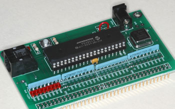
The 4520 board was developed at NU as a versatile prototyping platform for incorporating PICs. It offers a bare minimum environment for getting a PIC running, plus space for your circuits. In a few minutes you can assemble a 4520 board, and be ready to start programming it. Shown here is the version that plugs into a solderless breadboard, for prototyping.
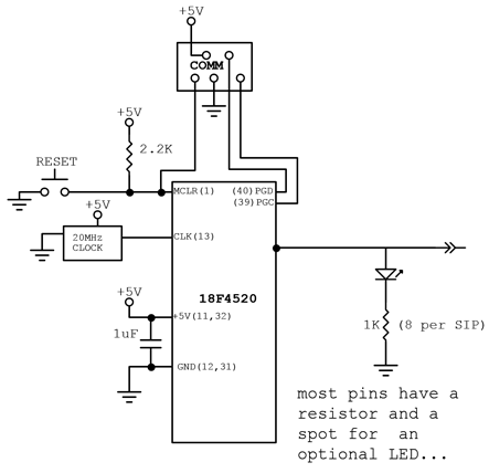
Circuit diagram of the 4520 prototyping board
The circuitry on the board includes an optional voltage regulator, a reset button, a programming port, and power indicator light. And the PIC microcontroller of course.
Also built in are the current limiting resistors for up to 32 LEDs, and places to put LED indicators on as many of those lines as you wish. These are intended to be used as diagnostics. The current limiting resistors are compactly packaged in a 9-pin SIP, containing 8 resistors and a common ("bussed") pin, which we ground.
When a line is used as a digital input or output you probably want to insert an LED to show its state. When a line is used as an analog input you probably do not want to load it down with an unnecessary LED.
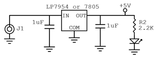
Regulator or no regulator?
If you are going to use a regulated +5V supply, you don't need the regulator chip: just jumper pin 1 to pin 3 instead of inserting the regulator. If you use a supply not much greater than +5V you will choose the LP7954it regulator, which needs only a small voltage headroom (excess of input voltage over desired output voltage) but handles only a maximum of 0.25A. The 7805 series regulators require ~2 volts of headroom but can handle up to 1.5A. In either case you may find that a heatsink is needed.
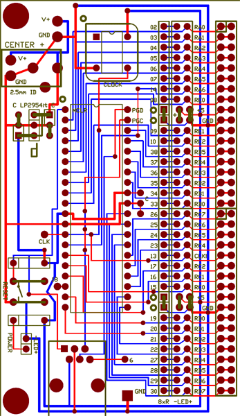
Layout of the 4520 PCB
Most of the 40 pins of the PIC are brought out to labeled connection points.
The corresponding pin number of the PIC is shown (01-40) and also the name of the pin (e.g. RA1). Most pins have many uses and thus many names, but only one name is shown.
You can solder to these connection points, or insert a dual-row connector for a ribbon cable header, or a single-row connector to insert the board into a solderless breadboard, or you can solder terminal strips onto the board.
Here is a full size gif of the board
, also showing the prototyping area.
The board is intended to be cut in half, providing one part for insertion into a solderless breadboard, and another part for more reliable solderboard construction.
The next step better yet is to to make a printed circuit board with your circuit on it as well as the PIC. If starting with the protoboard's layout is useful to you, you can find it here:
4520 board in traxmaker format.
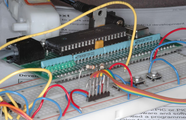
Using solderless breadboard with the 4520 board
Shove it in there. Hard. See photo below.
You can run wires from the +5 and ground connections on 4520 board to the red and blue rails on the solderles breadboard.
