Difference between revisions of "PIC18F4520: PWM Motor Control"
From Mech
Jump to navigationJump to search| Line 4: | Line 4: | ||
<br><br> |
<br><br> |
||
[[Image:4520pindiagramPWM.jpg||center]] |
[[Image:4520pindiagramPWM.jpg||center]] |
||
<br> |
|||
<br> |
|||
==Unidirectional Motor Control== |
|||
This section will detail how to set up a simple program and circuit to control a motor using a PIC microcontroller and PWM. |
|||
===Sample Code=== |
|||
==Bidirectional Motor Control== |
|||
Revision as of 10:19, 27 June 2007
Pulse Width Modulation, or PWM, is a technique used to vary the average magnitude of a signal by changing its duty cycle (the proportion of time that a signal is active or "high"). For a moe in-depth introduction to PWM motor control click here.
Available Pins
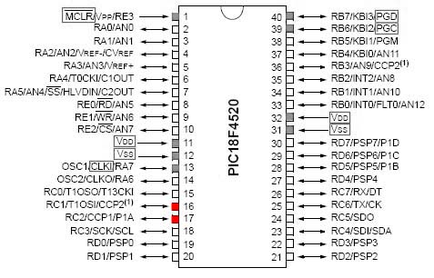
The PIC18F4520 is capable of outputing a PWM (Pulse Width Modulation) signal on two separate channels: CCP1 and CCP2 (shown below). The red pins have the capability of outputing PWM, while the grey are usually committed to communication or power.
Unidirectional Motor Control
This section will detail how to set up a simple program and circuit to control a motor using a PIC microcontroller and PWM.
