Difference between revisions of "Passive Filters"
| Line 1: | Line 1: | ||
==RL Circuits== |
|||
__TOC__ |
|||
===Charging=== |
|||
We can build some very simple filters out of a capacitor and a resistor. A filter will block some frequencies, while admitting others. |
|||
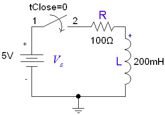
If the inductor is initially uncharged and we want to charge it by inserting a voltage source <math>V_s</math> in the RL circuit: |
|||
[[Image:RL_charge_schematic.gif]] |
|||
Better filters can be made out of op-amps. |
|||
The inductor initially has a very high resistance, as energy is going into building up a magnetic field. Once the magnetic field is up and no longer changing, the inductor will act like a short circuit. The current at steady state will be equal to <math>I_0=V_s/R</math>. Since the inductor is acting like a short circuit at steady state, the voltage across the inductor then will be 0. The current through the inductor is given by: |
|||
==Low-Pass Filters (LPF)== |
|||
A low pass filter will admit lower frequencies and block out high ones. This can help us smooth out our signals and get rid of high frequency noise. |
|||
<math>i_L(t)=I_0(1-e^{-\frac{R}{L}t})</math> |
|||
We can make one by hooking up our capacitor and resistor like this: |
|||
[[Image:RC_LPF_schematic.jpg]] |
|||
===Discharging=== |
|||
When set R=500Ω and C=2nF, and hook up an AC voltage source, the voltage we see at <math>V_out</math> depends on the frequency of our source. Here is a plot of the frequency response of the filter, on a logarithmic scale from 10Hz to 10MHz: |
|||
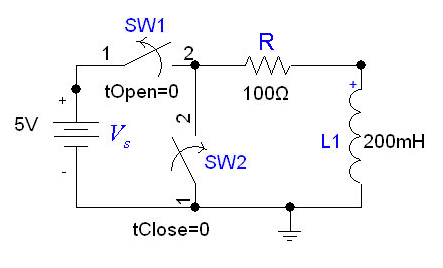
In the following circuit, the inductor initially has current <math>I_0=V_s/R</math> flowing through it; we replace the voltage source with a short circuit at <math>t=0</math>. |
|||
[[Image: |
[[Image:RL_discharge_schematic.gif]] |
||
After we cut out the voltage source, the voltage across the inductor will be <math>I_0*R</math>, but the higher voltage will be at the negative terminal of the inductor. Thus, <math>I_0=-V/R</math>. The the current flowing through the inductor at time ''t'' is given by: |
|||
As we can see, the filter blocks the higher frequncies. |
|||
<math>i_L(t)=I_0e^{-\frac{R}{L}t}</math> |
|||
Since a square wave is made out of a superposition of many sine waves, the low-pass filter will block the sine waves with higher frequencies. Our input and output will look like: |
|||
where <math>I_0=-V_s/R</math>. |
|||
[[Image:RC_LPF_square_wave.jpg]](C=200uF, R=500Ω) |
|||
The ''time constant'' for the RL circuit is equal to <math>L/R</math>. |
|||
==High-Pass Filter (HPF)== |
|||
A high pass filter will block out lower frequencies while letting high frequencies through. The output will respond more strongly to changes in the input signal, such as that coming from a motion detector. |
|||
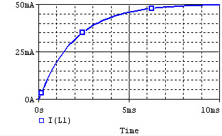
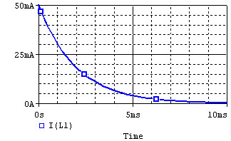
The voltage and current of the inductor for the circuits above are given by the graphs below, from ''t=0'' to ''t=5L/R''. The voltage is measured at the "+" terminal of the inductor, relative to the ground. A positive current flows into the inductor from this terminal; a negative current flows out of this terminal.: |
|||
We can make a simple high-pass filter by hooking up our capacitor and resistor like this: |
|||
{| border="1" cellspacing="0" cellpadding="5" align="center" |
|||
[[Image:RC_HPF_schematic.jpg]] |
|||
|+'''Inductor''' |
|||
|- |
|||
! !!Voltage !! Current |
|||
|- |
|||
!Charge !! [[Image:RL_charge_voltage.gif]] || [[Image:RL_charge_current.gif]] |
|||
|- |
|||
!Discharge !! [[Image:RL_discharge_voltage.gif]] || [[Image:RL_discharge_current.gif]] |
|||
|- |
|||
|} |
|||
Remember that for an inductor, <math>v(t)=L*di/dt</math>. Note that the voltage across the inductor can change instantly at ''t=0'', but the current changes slowly. |
|||
The frequncy response of a filter with R=500Ω and C=2nF looks like this: |
|||
[[Image:RC_HPF_frequency_Response.jpg]] |
|||
This time, the filter blocks the lower frequencies. |
|||
When we put a square wave though the filter, the resulting waveform looks like this: |
|||
[[Image:RC_HPF_square_wave.jpg]](C=200uF, R=500Ω) |
|||
Notice that when the input voltage drops to zero, the output voltage becomes negative. This is because the capacitor is discharging, and forcing the current backwards. |
|||
Revision as of 16:07, 20 June 2006
RL Circuits
Charging
If the inductor is initially uncharged and we want to charge it by inserting a voltage source in the RL circuit:
The inductor initially has a very high resistance, as energy is going into building up a magnetic field. Once the magnetic field is up and no longer changing, the inductor will act like a short circuit. The current at steady state will be equal to Failed to parse (MathML with SVG or PNG fallback (recommended for modern browsers and accessibility tools): Invalid response ("Math extension cannot connect to Restbase.") from server "https://wikimedia.org/api/rest_v1/":): {\displaystyle I_0=V_s/R} . Since the inductor is acting like a short circuit at steady state, the voltage across the inductor then will be 0. The current through the inductor is given by:
Failed to parse (MathML with SVG or PNG fallback (recommended for modern browsers and accessibility tools): Invalid response ("Math extension cannot connect to Restbase.") from server "https://wikimedia.org/api/rest_v1/":): {\displaystyle i_L(t)=I_0(1-e^{-\frac{R}{L}t})}
Discharging
In the following circuit, the inductor initially has current Failed to parse (MathML with SVG or PNG fallback (recommended for modern browsers and accessibility tools): Invalid response ("Math extension cannot connect to Restbase.") from server "https://wikimedia.org/api/rest_v1/":): {\displaystyle I_0=V_s/R} flowing through it; we replace the voltage source with a short circuit at .
After we cut out the voltage source, the voltage across the inductor will be Failed to parse (MathML with SVG or PNG fallback (recommended for modern browsers and accessibility tools): Invalid response ("Math extension cannot connect to Restbase.") from server "https://wikimedia.org/api/rest_v1/":): {\displaystyle I_0*R} , but the higher voltage will be at the negative terminal of the inductor. Thus, Failed to parse (MathML with SVG or PNG fallback (recommended for modern browsers and accessibility tools): Invalid response ("Math extension cannot connect to Restbase.") from server "https://wikimedia.org/api/rest_v1/":): {\displaystyle I_0=-V/R} . The the current flowing through the inductor at time t is given by:
Failed to parse (MathML with SVG or PNG fallback (recommended for modern browsers and accessibility tools): Invalid response ("Math extension cannot connect to Restbase.") from server "https://wikimedia.org/api/rest_v1/":): {\displaystyle i_L(t)=I_0e^{-\frac{R}{L}t}}
where Failed to parse (MathML with SVG or PNG fallback (recommended for modern browsers and accessibility tools): Invalid response ("Math extension cannot connect to Restbase.") from server "https://wikimedia.org/api/rest_v1/":): {\displaystyle I_0=-V_s/R} .
The time constant for the RL circuit is equal to Failed to parse (MathML with SVG or PNG fallback (recommended for modern browsers and accessibility tools): Invalid response ("Math extension cannot connect to Restbase.") from server "https://wikimedia.org/api/rest_v1/":): {\displaystyle L/R} .
The voltage and current of the inductor for the circuits above are given by the graphs below, from t=0 to t=5L/R. The voltage is measured at the "+" terminal of the inductor, relative to the ground. A positive current flows into the inductor from this terminal; a negative current flows out of this terminal.:
| Voltage | Current | |
|---|---|---|
| Charge | 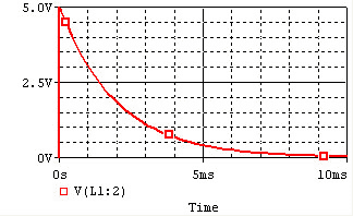 |
|
| Discharge | 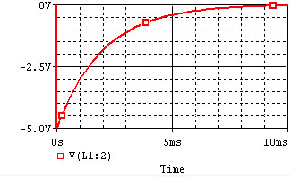 |
|
Remember that for an inductor, Failed to parse (MathML with SVG or PNG fallback (recommended for modern browsers and accessibility tools): Invalid response ("Math extension cannot connect to Restbase.") from server "https://wikimedia.org/api/rest_v1/":): {\displaystyle v(t)=L*di/dt} . Note that the voltage across the inductor can change instantly at t=0, but the current changes slowly.

