Difference between revisions of "FChronos"
| Line 6: | Line 6: | ||
It does this by synchronizing its system clock to microsecond precision with another computer on the same LAN using PTPv2 as a slave. Then, the device will generate timecodes which correspond to its own system clock and output the timecode along with a trigger pulse to the eSync. Since the eSync writes this timecode onto the NatNet packets, this allows direct translation of the NatNet timecode value to a system clock time when it arrives on the target computer. |
It does this by synchronizing its system clock to microsecond precision with another computer on the same LAN using PTPv2 as a slave. Then, the device will generate timecodes which correspond to its own system clock and output the timecode along with a trigger pulse to the eSync. Since the eSync writes this timecode onto the NatNet packets, this allows direct translation of the NatNet timecode value to a system clock time when it arrives on the target computer. |
||
==Operation== |
|||
[[Image:FChronos.svg|frame|c|right|fChronos timing diagram]] |
|||
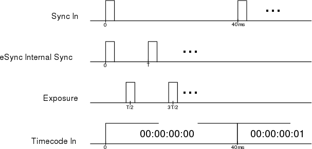
The device starts [http://ptpd.sourceforge.net/ ptpd] on boot as a clock slave. It will then synchronize to a master clock (which should be the control PC) to within about a microsecond of precision by doing a handshake with the master over the network at most once per second. It also starts a hard realtime process that reads its system time, and provides the trigger signal on GPIO 4, and the SMPTE timecode on GPIO 17 at 25 Hz. A full timing diagram is shown to the right, where the "Sync In" and "Timecode In" are the outputs of the fChronos to the [[eSync]]. |
|||
The sync and timecode signals are output at a rate of 25 Hz. The timecode has the logical format HH:MM:SS:FF, where the frames FF are in the range [0,24]. The [[eSync]] locks its internal clock to these frequencies, and allows us to specify a multiplicative factor to achieve a desired framerate. For our cameras, we find that this factor should be set to 14 (25 Hz * 14 = 350 fps) for best performance without dropping frames. This internal lock and multiplication gives the "eSync Internal Sync" signal in the diagram. The middle of the actual exposure happens at <math>T/2</math> seconds after the internal clock pulse. |
|||
==Hardware== |
==Hardware== |
||
Revision as of 09:14, 14 February 2014
The fChronos is a custom device meant to be attached to the eSync device to address certain deficiencies of the latter.
Purpose
The purpose of this device is to provide a way to get the true acquisition time of a frame of motion capture data. We need to do this in a high-speed system, because you simply cannot assume the time that a packet arrives is the same time that the exposure captured the data. Since the latency introduced by UDP and the OS is a random process with unacceptable delay and jitter (ms or more), we need a way to get the time of the actual acquisition of the data with (hopefully) microsecond precision.
It does this by synchronizing its system clock to microsecond precision with another computer on the same LAN using PTPv2 as a slave. Then, the device will generate timecodes which correspond to its own system clock and output the timecode along with a trigger pulse to the eSync. Since the eSync writes this timecode onto the NatNet packets, this allows direct translation of the NatNet timecode value to a system clock time when it arrives on the target computer.
Operation
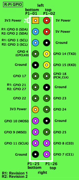
The device starts ptpd on boot as a clock slave. It will then synchronize to a master clock (which should be the control PC) to within about a microsecond of precision by doing a handshake with the master over the network at most once per second. It also starts a hard realtime process that reads its system time, and provides the trigger signal on GPIO 4, and the SMPTE timecode on GPIO 17 at 25 Hz. A full timing diagram is shown to the right, where the "Sync In" and "Timecode In" are the outputs of the fChronos to the eSync.
The sync and timecode signals are output at a rate of 25 Hz. The timecode has the logical format HH:MM:SS:FF, where the frames FF are in the range [0,24]. The eSync locks its internal clock to these frequencies, and allows us to specify a multiplicative factor to achieve a desired framerate. For our cameras, we find that this factor should be set to 14 (25 Hz * 14 = 350 fps) for best performance without dropping frames. This internal lock and multiplication gives the "eSync Internal Sync" signal in the diagram. The middle of the actual exposure happens at seconds after the internal clock pulse.
Hardware
It is a (model B) Raspberry Pi running the Machinoid hard RTOS distribution.
Software
It runs a custom piece of software that reads system time, and bitbangs the trigger signal on GPIO 4, and the SMPTE timecode on GPIO 17 at 25 Hz.


