Difference between revisions of "Brushless DC Motors"
| Line 5: | Line 5: | ||
===Commutation Circuitry=== |
===Commutation Circuitry=== |
||
[[File:Mosfet_H-Bridge.png|200px|right|Mosfet H-Bridge Setup]] |
[[File:Mosfet_H-Bridge.png|200px|right|Mosfet H-Bridge Setup]] |
||
Unlike a DC motor, which is automatically commutated by the rotation of its brushes, a brushless DC motor can only be commutated by changing the voltage level on each of its three inputs |
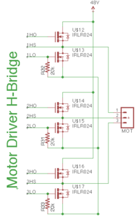
Unlike a DC motor, which is automatically commutated by the rotation of its brushes, a brushless DC motor can only be commutated by changing the voltage level on each of its inputs. For a three phase motor there are three inputs and during each phase of the commutation one input of the BLDC motor will be at the voltage supply level, one will be floating and one will be at ground. This can be accomplished using an H-bridge chip. For higher current applications the N-Channel MOSFET H-bridge configuration shown can be used. |
||
===Rotational Sensors=== |
|||
Because the controller must change the voltage levels on the motor inputs, the controller needs a way of determining the motor's rotational position. A typical motor will include a Hall Effect sensor encoder or some other type of rotary encoder. More advanced drive systems will use the back EMF in the coils to determine the rotor position. |
|||
To rotate the BLDC motor, the stator windings must be energized in a sequence. The commutation circuitry needs to know the rotor position in order to energize the correct winding. A typical BLDC motor comes with a Hall Effect sensor encoder embedded in the stator. In a three phase motor there are three Hall sensors. Whenever the rotor magnetic poles pass near the Hall sensors, they give a high or low signal, indicating the N or S pole is passing near the sensors. Based on the combination of these three Hall sensor signals, the exact sequence of commutation can be determined. In a more advanced controller the position of the rotor is determined by the back EMF on the input lines. This method is called sensorless mode because it does not require the use of Hall Effect sensors. |
|||
==Commutation Pattern== |
==Commutation Pattern== |
||
Latest revision as of 10:26, 18 September 2013
Overview
Brushless DC (BLDC) motors are similar to Brushed DC Motors, except the commutation is done electronically, and the permanent magnets are on the rotor and the coils on the stator. Instead of using the brushes and the rotation of the commutator to power the coils, external circuitry is used. Brushless DC motors are generally more expensive and take extra effort in order to drive. However, BLDCs can be more efficient under light loads, typically have better power-to-weight ratios and produce less wear on internal components.
Commutation Circuitry
Unlike a DC motor, which is automatically commutated by the rotation of its brushes, a brushless DC motor can only be commutated by changing the voltage level on each of its inputs. For a three phase motor there are three inputs and during each phase of the commutation one input of the BLDC motor will be at the voltage supply level, one will be floating and one will be at ground. This can be accomplished using an H-bridge chip. For higher current applications the N-Channel MOSFET H-bridge configuration shown can be used.
Rotational Sensors
To rotate the BLDC motor, the stator windings must be energized in a sequence. The commutation circuitry needs to know the rotor position in order to energize the correct winding. A typical BLDC motor comes with a Hall Effect sensor encoder embedded in the stator. In a three phase motor there are three Hall sensors. Whenever the rotor magnetic poles pass near the Hall sensors, they give a high or low signal, indicating the N or S pole is passing near the sensors. Based on the combination of these three Hall sensor signals, the exact sequence of commutation can be determined. In a more advanced controller the position of the rotor is determined by the back EMF on the input lines. This method is called sensorless mode because it does not require the use of Hall Effect sensors.
Commutation Pattern
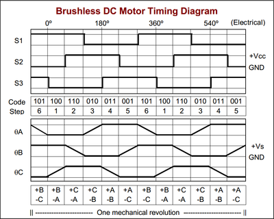
For a motor with a hall effect sensor encoder a typical commutation diagram is shown in the image to the right. The commutation diagram was taken from the Pittman Motor 4443S013 Datasheet. By reading the state of the three hall effect sensors the motor controller can set the state of the motor inputs.
References
- Wikipedia, "Brushless DC electric motor", http://en.wikipedia.org/wiki/Brushless_motors

