Northwestern Design Competition: Difference between revisions
From Mech
Jump to navigationJump to search
Content deleted Content added
NickMarchuk (talk | contribs) No edit summary |
NickMarchuk (talk | contribs) |
||
| Line 17: | Line 17: | ||
'''Milestone 1, due by 1/27''' |
'''Milestone 1, due by 1/27''' |
||
*If a pushbutton is pressed, read the value of a potentiometer and change the brightness of an LED to the corresponding value with PWM |
*If a pushbutton is pressed, read the value of a potentiometer and change the brightness of an LED to the corresponding value with PWM |
||
'''Workshop 2, |
'''Workshop 2, Thursday 2/9 6-7pm Tech L221, makeup Friday 2/10 9-11am Mechatronics Lab''' |
||
*Optical isolation for motors and RC servos |
*Optical isolation for motors and RC servos |
||
*Powering a motor with an h-bridge |
*Powering a motor with an h-bridge |
||
| Line 23: | Line 23: | ||
*Laser detection of retroreflective tape / Optical line detection |
*Laser detection of retroreflective tape / Optical line detection |
||
*2 1/2D design |
*2 1/2D design |
||
'''Milestone 2, Due week of Feb |
'''Milestone 2, Due week of Feb 20''' |
||
*Optically isolate a motor |
*Optically isolate a motor |
||
*Read a potentiometer and write its voltage to the LCD |
*Read a potentiometer and write its voltage to the LCD |
||
*Control the motor velocity based on the potentiometer reading |
*Control the motor velocity based on the potentiometer reading |
||
*Control an RC servo |
|||
*Mount a phototransistor to a laser and detect a scoring zone OR detect a line of electrical tape on white paper |
|||
*Detect a 3/4" wide black line on white paper with a phototransistor and LED |
|||
'''Workshop 3, Week of Feb 27''' |
'''Workshop 3, Week of Feb 27''' |
||
*Line following |
*Line following |
||
Revision as of 10:39, 6 February 2012
DC2012
Equipment
- NU32, USB cable, 6V power supply
- 2 drive motors, 2 motor mounts, 2 wheels
- 2 large RC servos, 2 small RC servos
- red lasers
- 2 12"x24"x1/8" acrylic sheets
Workshop 1, Wednesday 1/18 5:30-7pm Tech L221, makeup Thursday 1/19 9-11am Mechatronics Lab
- How to program in MPLABX
- How to use the bootloader to put code on the NU32
- Digital output I/O (read a button and flash an LED)
- Analog input
- PWM output
- Sample code: Sample code for Workshop 1
Milestone 1, due by 1/27
- If a pushbutton is pressed, read the value of a potentiometer and change the brightness of an LED to the corresponding value with PWM
Workshop 2, Thursday 2/9 6-7pm Tech L221, makeup Friday 2/10 9-11am Mechatronics Lab
- Optical isolation for motors and RC servos
- Powering a motor with an h-bridge
- Writing to the 16x2 character LCD
- Laser detection of retroreflective tape / Optical line detection
- 2 1/2D design
Milestone 2, Due week of Feb 20
- Optically isolate a motor
- Read a potentiometer and write its voltage to the LCD
- Control the motor velocity based on the potentiometer reading
- Control an RC servo
- Detect a 3/4" wide black line on white paper with a phototransistor and LED
Workshop 3, Week of Feb 27
- Line following
- Laser cutting
- Line following and detecting the crate
Milestone 3, Due week of Mar 5
- Finish laser cutter training
- First draft of a robot chassis
- One of the following:
- Follow a line
- Detect a crate or scoring zone and drive towards it
DC2011
Milestone 1
- On a button press, read the value of a potentiometer and change the brightness of an LED accordingly using PWM. Note: Do not use an h-bridge or motor as previously assigned.
- Due before Workshop 2 on Wed, 2/9.
- Sample code from Workshop 1
Milestone 2
- Due before Workshop 3 on Wed, 2/23.
- Goals:
- Use code from NU32v2: Nokia 5110 LCD and NU32v2: Analog Input to read a potentiometer and print the voltage to the Nokia 5110
- Optically isolate a motor and control its velocity based on the potentiometer reading
- Do 1 of the following:
- Mount a phototransistor to a laser and detect a cake OR
- Detect a line of electrical tape on white paper with an optoreflector
- Datasheets
- HBridge_L293D.pdf - H-bridge for driving a DC motor
- Optocoupler_A847.pdf - Optocoupler to optically isolate your H-bridge
- HexInverter_74HC04.pdf - Inverting chip to digitize optocoupler output
- Optoreflector_OPB740.pdf - Optoreflector to detect lines or color
- Optoreflector_QRE1113.pdf - Optoreflector to detect lines or color
- Phototransistor_SFH310.pdf - Phototransistor to detect lines, color, or laser reflections
- Notes
- DC2011_WS2_OpticalIsolation.pdf - How to optically isolate an h-bridge and servo motor using the A847 and 74HC04
- DC2011_WS2_OpticalSensors.pdf - How to use the SFH310 to detect a cake and use the OPB740 or QRE1113 for line following
- DC2011_WS2_Code.zip - Example code for the NU32v2 that will:
- Control a DC motor hooked up to an optically isolated h-bridge, and control an optically isolated RC servo motor
- Respond to serial commands to control the motors, write to the Nokia 5110, and read two analog signals
Milestone 4
- Due before Wed, 3/16
- Finish laser training, at least one person per team
- Construct a prototype chassis for your robot
- Do one of the following:
- Follow part of the line on the 36" x 96" printout of this pdf
- Detect a cake somewhere on the floor and drive to it
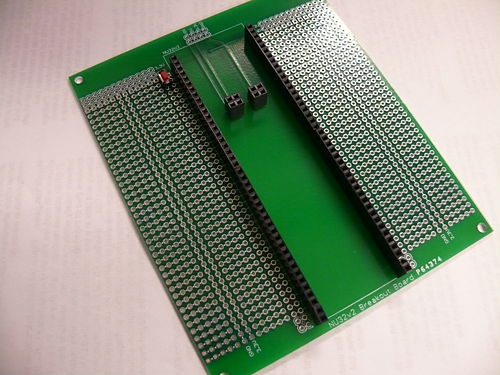
Breakout Boards
- Image of the breakout boards
- Circuit schematic of the breakout boards
- This board contains:
- A spot to plug in the NU32v2 with some prototyping area
- The optical isolation circuit with some prototyping area, the same size as the NU32v2 breakout board so it can be stacked on top
- 8 SFH310 with LED breakout boards
- 4 SFH310 with laser diode breakout boards
- 1 LIS352AX accelerometer breakout board
- 1 LSM303DHL tilt-compensated compass breakout board
- 1 LPY550AL gyroscope breakout board
- 1 LS7366R encoder decoder breakout board
- 1 TCS3103 color sensor breakout board
- How to use the boards:
Solder female header pins to the NU32v2 Breakout Board so that you can plug in and remove your NU32v2 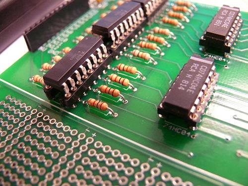
Solder sockets to the Optically Isolated Motor Board so you can remove burnt out chips 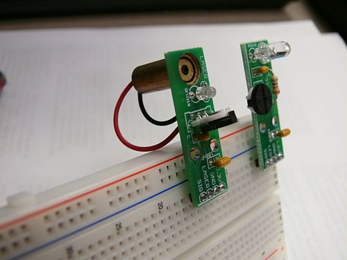
The LED and Laser Phototransistor breakout boards will make it easier to attach wires to the sensors 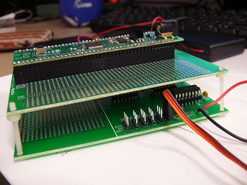
You can stack the NU32v2 breakout board with the Optically Isolated board


Brochure for 2011
Previous Years
Wiki pages on sensors, actuators, programming, and microcontrollers: use pages below
- Parts in the DC2008 quick start pack
- PIC C intro slides, as presented 2008/01/24 (pdf)
- PIC interfacing slides, as presented 2008/01/28 (pdf)
- Link to all sample PIC code here.
Sensors and actuators for DC
- Solderless Breadboard & wiring that works
- Using LEDs & IREDs
- Using a laser
- Infrared reflectivity
- Using phototransistors
- Sensing optical tape
- Comparators : the analog digital interface
- Faulhaber MiniMotor SA gearmotor with encoder, as well as the local wiki page
- Adding a magnetic encoder to a GM3 Gearmotor
- Using magnetic switches (Hall Effect)
- Driving high-current devices: several options
- Driving a Stepper Motor
- Driving an RC Servo
- Accelerometers
- Strain gauges
- Basic Stamp Microcontroller Not recommended for DC2008
- NiMH rechargable batteries and chargers
Prof. Peshkin's favorite datasheets