Difference between revisions of "Butterfly Rolling Manipulation"
WilliamFan (talk | contribs) |
WilliamFan (talk | contribs) |
||
| Line 41: | Line 41: | ||
*14N002 diodes (4) |
*14N002 diodes (4) |
||
*LS7083 decoder |
*LS7083 decoder |
||
*Pittman GM8224 motor with 19.5:1 gearhead and 500 line encoder |
*[[Pittman GM8224 motor with 19.5:1 gearhead and 500 line encoder|Pittman GM8224 motor]] |
||
*Protoboard/breadboard |
*Protoboard/breadboard |
||
Revision as of 19:02, 18 March 2010
Overview
Our project was to perform a contact juggling move called the "butterfly" on a circular disc. Papers have been submitted on the shape of the butterfly apparatus, along with the general motion in order to perform the move. Implementing these papers for the first time in full gravity, we were able to design the circuitry, build the system, and test it in a matter of four weeks. The below wiki will explain our process step by step.
Team Members
Eric Bell (Mechanical Engineer, 2010)
William Fan (Mechanical Engineer, 2011)
Ben Kolodner (Mechanical Engineer, 2010)
Mechanical Design
In order to achieve the butterfly motion, a well designed, non-moving base and setup must be fabricated. Listed below shows the Bill of Materials, How we chose the shape of the butterfly, how it was mounted, and finally the design and iterations of the disc system.
Bill of Materials
The Hand:Butterfly Shape
The Mount
The Roller
Circuit
Parts List
- PIC32 NU32 Board + PIC USB cable
- RS232 cable
- HD44780 LCD
- 5k potentiometer (1)
- 100 ohm resistor (3)
- 2.2 kohm resistor (1)
- 3.3 kohm resistor (1)
- 0.1uF capacitor (5)
- L298N H-bridge
- 14N002 diodes (4)
- LS7083 decoder
- Pittman GM8224 motor
- Protoboard/breadboard
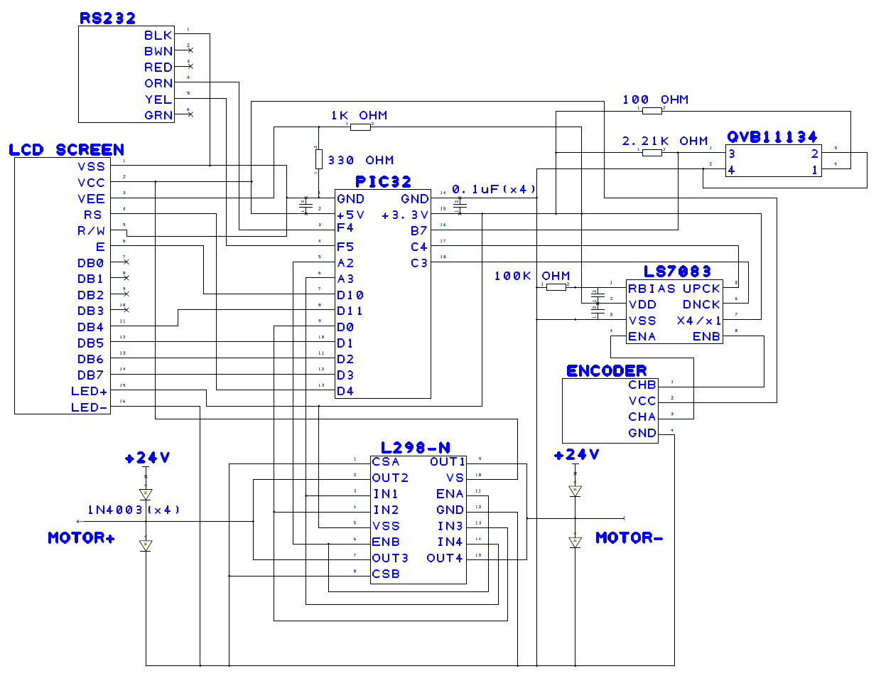
Circuit Diagram
Motor
A Pittman GM8724S017 24V motor was chosen for the apparatus. Information for the motor can be found [here]. Originally, our motor did not use a gear-head in order to reduce backlash. However, this continuously burned out our H-Bridges, so a motor with a 19.5:1 gear-head ratio was selected to provide additional torque.
H-bridge disclaimer
Code
Processing
The purpose of the processing code is to plot the actual movement of the motor against the reference trajectory. The code produces a reference trajectory based on the given equation, a constant time interval, and a k-value and produces 2000 reference points for the motor to follow. Because processing plots one data point per pixel, only every other reference point is saved into an array in the pic. At every reference point, the encoder reads the position and also records this actual position at every other reference point into a separate array. These arrays are fed from the pic into a computer using an RS232 cable when the “read data” button is pushed in the processing GUI. Processing then plots these arrays.
Processing is also used to reset the hand. By pushing the reset button in the processing GUI, processing activates an interrupt which tells the hand to reset using the light sensor and run the main code again.
<insert graph>
Based on the graphs created in processing, the PD control was very effective in controlling the motor. Minor offsets occurred consistently at the beginning and end of each run due to backlash from the motor, but the actual position was very close to the reference trajectory a majority of the time.
Results
Next Steps
- Eliminate backlash via gearless motor
- Sense position of the disc using copper tape and resistive wire
- Implement PID control on motor position, along with control of PID using sensing of disc
- Test other butterfly shapes with lower or higher curvature
- Test other disc shapes with different center of masses and weights
- Replace H-Bridges with nicer ones that can take higher amperage


