Difference between revisions of "Butterfly Rolling Manipulation"
WilliamFan (talk | contribs) |
WilliamFan (talk | contribs) |
||
| Line 28: | Line 28: | ||
==Circuit Diagram== |
==Circuit Diagram== |
||
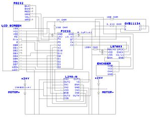
[[Image:ButterflyCircuitDiagram.jpg|thumb|center|Butterfly Circuit Diagram.]] |
[[Image:ButterflyCircuitDiagram.jpg|upright:3|thumb|center|Butterfly Circuit Diagram.]] |
||
==Motor== |
==Motor== |
||
Revision as of 00:22, 18 March 2010
Overview
Team Members
Eric Bell (Mechanical Engineer, 2010)
William Fan (Mechanical Engineer, 2011)
Ben Kolodner (Mechanical Engineer, 2010)
Mechanical Design
Parts List
The Hand:Butterfly Shape
The Mount
The Roller
Circuit
Parts List
Circuit Diagram
Motor
H-bridge disclaimer
Code
Processing
The purpose of the processing code is to plot the actual movement of the motor against the reference trajectory. The code produces a reference trajectory based on the given equation, a constant time interval, and a k-value and produces 2000 reference points for the motor to follow. Because processing plots one data point per pixel, only every other reference point is saved into an array in the pic. At every reference point, the encoder reads the position and also records this actual position at every other reference point into a separate array. These arrays are fed from the pic into a computer using an RS232 cable when the “read data” button is pushed in the processing GUI. Processing then plots these arrays.
Processing is also used to reset the hand. By pushing the reset button in the processing GUI, processing activates an interrupt which tells the hand to reset using the light sensor and run the main code again.
<insert graph>
Based on the graphs created in processing, the PD control was very effective in controlling the motor. Minor offsets occurred consistently at the beginning and end of each run due to backlash from the motor, but the actual position was very close to the reference trajectory a majority of the time.

