Difference between revisions of "Haptic Gaming System"
MeganWelker (talk | contribs) |
MeganWelker (talk | contribs) |
||
| Line 42: | Line 42: | ||
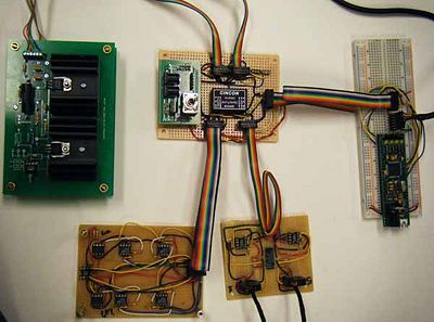
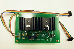
[[Image:CircuitsTeam22.jpg|thumb|400px|Circuitry.|center]] |
[[Image:CircuitsTeam22.jpg|thumb|400px|Circuitry.|center]] |
||
===PIC Configuration=== |
|||
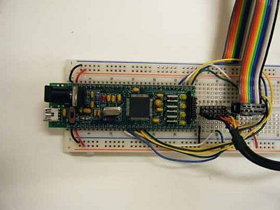
[[Image:PICWiringTeam22.jpg|thumb|400px|center]] |
|||
===Whatever this is === |
|||
what it does |
|||
its circuit |
|||
<br clear=all> |
|||
{| border="0" |
|||
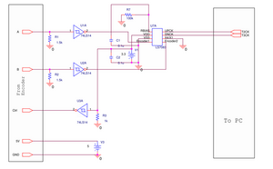
|[[image:Circut1Team22meg.jpg|thumb|300px|center]] |
|||
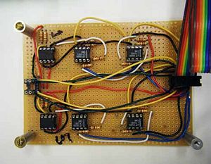
|[[image:PictureofCircut1Team22.jpg|thumb|300px|center]] |
|||
|} |
|||
<br clear=all> |
|||
=== thing 2 === |
|||
what it does |
|||
its circuit |
|||
<br clear=all> |
|||
{| border="0" |
|||
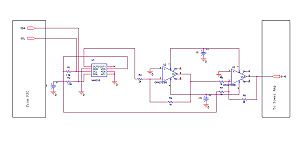
|[[image:Circut2Team22meg.jpg|thumb|300px|center]] |
|||
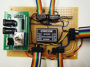
|[[image:PictureofCircut2Team22.jpg|thumb|300px|center]] |
|||
|} |
|||
<br clear=all> |
|||
=== Motor Control === |
|||
how it controls it |
|||
its circuit |
|||
<br clear=all> |
|||
{| border="0" |
|||
|[[image:MotorControlCircutTeam22.jpg|thumb|300px|center]] |
|||
|[[image:PictureofMotorControlCircutTeam22.jpg|thumb|300px|center]] |
|||
|} |
|||
<br clear=all> |
|||
==Software== |
==Software== |
||
Revision as of 16:38, 17 March 2010
Overview
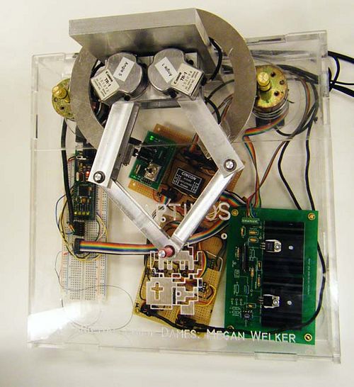
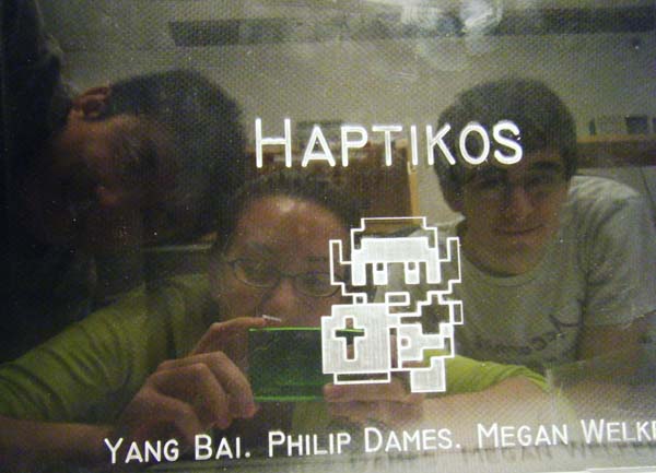
Haptikos is an interactive gaming system that allows the user to physically feel a virtual world. The player controls the cursor by moving the red joystick. Two games were created to test the feedback system. The first, the player assumes the character of LINK (from Zelda) and jumps through a side-scrolling level collecting rupees and avoiding red boxes. The second involves feeling out the virtual shape with nothing other than a blue position dot and a blank screen. The answer can be seen by pushing R.
The Team
- Yang Bai (Mechatronics Masters Student)
- Philip Dames (Mechanical Engineering MS/BS)
- Megan Welker(Mechanical Engineering BS/BM)
Mechanical Design
Existing System
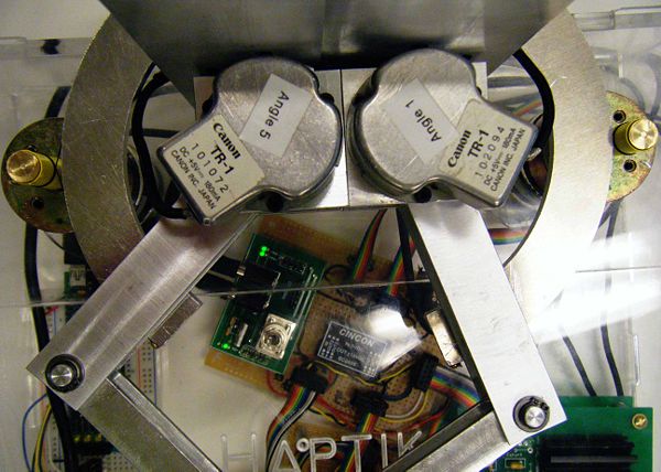
Haptikos is a modification from a previous pentagraph configuration. This allows for the free point to be able to freely move in a fixed two-dimensional plane. There are two Canon TR-36 optical encoders with a 3600 count/rev in x1 mode mounted on top of the stationary pivot.(see below) They are used to track the angle of the larger bars and calculate the position of the free point.
System Modifications
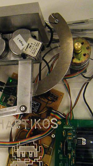
The existing system had the capability to accurately tell where the free point was in space, but could not put any force on that point. A Pittman 700935 motorwas attached to each of the larger bars in the back of the pentagraph using a capstan configuration.
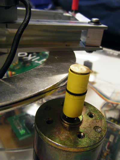
The capstan was created by milling two arcs out of Aluminum and then attaching one arc end to the furthest point from the backboard on each bar. A piece of heavy duty thread was set into the groove of the outer side of the arc and secured by screws on either side. To connect the capstan to the Motor, the thread was merely wound around the shaft three times and replaced tight into the groove. (see below)
The gear ratio the arc applies to the motor is approximately 14.7 to 1. (Radius of arc/ Radius of Capstan Drive)
Electrical Design
PIC Configuration
Whatever this is
what it does
its circuit
thing 2
what it does
its circuit
Motor Control
how it controls it
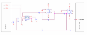
its circuit
