Difference between revisions of "Conservation of Angular Momentum Locomotion Robot (Fluffbot)"
| Line 62: | Line 62: | ||
==== Chassis ==== |
==== Chassis ==== |
||
The base of the chassis is made from a sheet of 1/4 inch clear Acrylic. It needed to be large enough to hold the motors, two batteries, and two circuit boards. In order to reduce the weight of the design, the base was cut into a triangle with wheels to be placed at each corner. Four small holes were cut at the front and at the middle of the base to allow the motor to be secured, and one larger hole was cut for a bearing to be pressed into place for the front steering wheel. [[Media:Dimensioned_Drawing_of_Chassis.pdf]] |
The base of the chassis is made from a sheet of 1/4 inch clear Acrylic. It needed to be large enough to hold the motors, two batteries, and two circuit boards. In order to reduce the weight of the design, the base was cut into a triangle with wheels to be placed at each corner. Four small holes were cut at the front and at the middle of the base to allow the motor to be secured, and one larger hole was cut for a bearing to be pressed into place for the front steering wheel. [[Media:Dimensioned_Drawing_of_Chassis.pdf.end|Dimensioned_Drawing_of_Chassis]] |
||
==== Steering Assembly ==== |
==== Steering Assembly ==== |
||
Revision as of 14:38, 17 March 2010
Overview
Flufbot uses conservation of angular momentum to move forward or backward, by controlling the acceleration of a momentum wheel and the angle of a steering wheel.
Team Members
//insert team picture
- Tyler Johnson - Mechanical Engineer - Class 2011
- Noah Pentelovitch - Mechanical Engineer - Class 2010
- Ren Chung (RC) Yu - Electrical Engineer - Class 2010
Concept Overview
Instead of using motors to directly drive its motion forward, Fluffbot uses the basic principal of conservation of angular momentum. When an object with a high moment of inertia is accelerated about an axis, angular momentum in the direction of motion is immediately created. When this happens, angular momentum in the opposing direction is also produced. The resulting motion from this "reaction" momentum can be transferred to ground through a rigid fixture, or this resulting motion could be controlled and channeled into a desirable form as shown with Fluffbot.
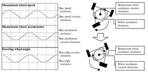
When the large flywheel on Fluffbot accelerates clockwise in the horizontal plane, the body attempts to conserve the zero angular momentum of the system by rotating around the same axis in a counter clockwise direction. Motion forward or backward by Fluffbot is made possible by the steering of the front wheel. There are three conditions for the steering wheel to be in, and three corresponding effects:
1) Wheel is aligned straight ahead - In this scenario, friction between the front wheel and the the ground prevent any rotation along the robot's main axis of rotation. Any acceleration of the momentum wheel in this arrangement will result in no movement of Fluffbot.
2) Wheel is turned to the left - When the momentum wheel accelerates in a clockwise direction, the chassis will attempt to rotate to the left. Because the front wheel is turned to the left, a portion of this rotation will be allowed to occur around a pivot point perpendicular to the direction the wheel is pointed. This gives the overall effect of turning Fluffbot to the left and moving it slightly forward. If the momentum wheel were to accelerate in the opposite direction (counter clockwise) while the front wheel is steering left, the result would be to turn Fluffbot to the right and send in moving backward.
3) Wheel is turned to the right - This exhibits the same behavior as when the front wheel is turned to the left, however, the direction of rotation for the momentum wheel and the chassis are reversed.
In order to control the motion of Fluffbot and to send it in a straight direction, the momentum wheel accelerates back and forth sinusoidally as the front wheel turns left to right with the same sinusoid. To reverse the direction that Fluffbot travels, simply put the front wheels control wave 180˚ out of phase with the control wave for the momentum wheel. Fluffbot is also able to steer left and right by controlling the amplitude and range of the front steering wheel.
Mechanical Design
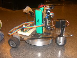
The Fluffbot has all of its circuitry and mechanical components confined to a single chassis. The chassis is an arrow shape and is mounted on three wheels attached to the bottom of the chassis. The two rear wheels are fixed, while the front wheel is free to rotate and is mounted on a fork and coupled to a servo, which controls its turning angle. A momentum wheel is fixed underneath the center of the chassis to a motor which is mounted on top. All circuitry and power sources are mounted on the top of the chassis as well.
Mechanically, the Fluffbot is designed for minimum chassis weight and maximum torque generated by the momentum wheel. The momentum wheel is mounted directly in the center of the three wheels so that the torque is distributed evenly. The wheels use press-fit ball bearings mounted on fixed axles to achieve minimum friction when rolling. The front-wheel fork is mounted to the chassis through a ball bearing to reduce frictional force on the servo motor.
Parts List
- Motors: Futaba S3004 standard ball bearing RC servo motor, Mechatronics Lab - Pittman _____ Motor ____ gear head, Mechatronics Lab
- Wheels: Machined from Aluminum 2" 6061 rod stock
- Momentum Wheel: Machined from 6" Aluminum 6061 rod stock
- Tires: Shop Stock rubber wheel coverings
- Wheel Fork: Machined from aluminum 6061 rod stock
- RC Servo-Shaft Coupler: Split clamp to Futaba S3004 coupler, ServoCity.com
- Chassis: laser cut from 1/4 inch 12"x12" clear acrylic
- Axels: _________
- Bearings: _______
- Fasteners: 10-32 set screw for securing the momentum wheel to the motor, 4-40 round-head screws for securing motor to the chassis
- Velcro: To attach battery packs and housing to the chassis
- Adhesives: Acrylic Epoxy for Servo Holder, Superglue for rear wheel mounts
Chassis
The base of the chassis is made from a sheet of 1/4 inch clear Acrylic. It needed to be large enough to hold the motors, two batteries, and two circuit boards. In order to reduce the weight of the design, the base was cut into a triangle with wheels to be placed at each corner. Four small holes were cut at the front and at the middle of the base to allow the motor to be secured, and one larger hole was cut for a bearing to be pressed into place for the front steering wheel. Dimensioned_Drawing_of_Chassis
Steering Assembly
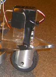
The front wheel was attached to the steering servo through a machined aluminum fork. The fork design was used (as opposed to a one-sided mount) so that the axis of rotation for the front wheel could be directly centered above the centerline of the wheel with relative ease.
The Futaba RC servo used for steering the front wheel was held in place by the servo-shaft coupler and by two pieces of acrylic. The servo was light enough that it could be supported by only the coupler. Two vertical pieces of acrylic prevented the servo from rotating as it turned the front wheel. A small piece of electrical tape kept the servo from backing off of the coupler while Fluffbot was operating. Dimensioned Drawing of Steering Fork
Momentum Wheel
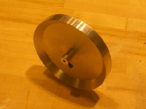
The momentum wheel is design specifically to increase the torque on the body. This was done by machining the wheel so that there was more weight on the outside of the wheel. The momentum wheel is made from Aluminum 6061. The shaft in the center of the momentum wheel connects to the shaft of the motor using a set screw. The motor connector shaft and the momentum wheel were made as one piece to increase rigidity and assure that the momentum wheel would be perfectly parallel to the chassis. The momentum wheel weighs about 1.3 lbs, which makes the torque on the motor above its maximum continuous torque rating. We felt that this would be alright because the motor is not running continuously at a high speed, but rather is accelerating and decelerating sinusoidally. The motor is also not running at maximum rpm. Dimensioned Drawing of Momentum Wheel
Wheels
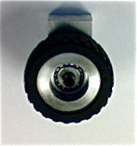
The wheels we used were specially machined out of Aluminum 6061 to fit treaded rubber tires we found in the machine shop. Aluminum was used instead of preformed plastic wheels because we could precisely machine the wheels to fit the design of the Fluffbot, rather than needing to design the Fluffbot around the wheels we had available. The wheels were designed to fit ____ ball bearings. The ball bearings were press fit into the center of the wheel. We used ball bearings so that the wheels would spin with minimal friction and thus less energy would be required to move the Fluffbot.
Battery and Electronics
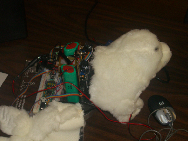
The batteries and circuit boards were attached to the top of the chassis using Velcro. The configuration of the batters as well as the placement of the circuit boards are meant so that a most of the weight on the chassis would be centered around the center of the momentum wheel and also so that we could easily place different housings (read: stuffed animals) around the Fluffbot.
Mechanical Debugging
Bearings are coming out of rear wheels: Re-machine wheels using a boring bar for the through-hole for the bearings. While boring out hole, check dimensions of the bearing being used and take small cuts, measuring after each pass, to assure that the hole diameter precisely matches that of the bearing.
Servo comes loose from servo coupler: Machine a set screw hole through the part of the coupler connecting to the servo and add a set screw to keep the servo in place
Electronics
Parts List
- PIC32 NU32 Board + PIC USB cable
- XBee Interface Board (2)
- RS232 cable
- LM7805C 5V regulator (2)
- 0.33uF capacitor
- 0.01uF capacitor
- LM338T adjustable voltage regulator (2)
- 5k potentiometer (2)
- 120 ohm resistor (2)
- 0.1uF capacitor (6)
- 1uF capacitor (2)
- L298N H-bridge
- 14N002 diodes (4)
- LS7083 decoder
- 100k ohm resistor
- Pittman GM8712G708-R3 24V motor
- Futaba S3004 RCservo motor
- Protoboard/breadboard
Electronics On Fluffbot
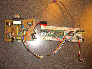
A 24V DC motor is used to control the momentum wheel. A RCservo motor is used to control the steering angle. An XBee Board is used to communicate between the Fluffbot and a PC.
The electronics block diagram (right picture) shows how each circuitry block connects to each other. The following links illustrate how each individual circuitry block is built:
- LM7805 5V regulator circuitry.
- LM338T adjustable voltage regulator circuitry for 18V and 3.3V.
- L298N H-bridge circuitry.
- LS7083 decoder circuitry. Note that our circuitry for the H-bridge is not the same as the one at this link.
Electronics At Computer
The second XBee Interface Board is connected to a computer using the RS232 cable. This enables the user to communicate wirelessly in real-time to the Fluffbot.
Code
There is a PIC32 code, compiled using MPLAB, as well as a Processing code. Download them: PIC code, Processing code.
The code does three things:
1) Sets motion parameters.
2) Controls acceleration and direction of the momentum wheel.
3) Controls angle of the steering wheel.
1) Sets motion parameters
Depending on the "type" of seal chosen, Fluffbot exhibits different styles of motion. The styles of motion are changed by changing the maximum angle of the steering wheel (amplitude) and by changing the rate at which the momentum wheel and steering wheel change direction (frequency).
There are three motion styles to choose from:
- Seal on land (medium amplitude, high frequency)
- Seal in water (low amplitude, medium frequency)
- Seal on ice (high amplitude, medium frequency)
Steps to change motion parameters:
- From a computer, using a Processing GUI, the user chooses between seal on land, in water, and on ice. The users choices are transmitted wirelessly to the Fluffbot.
- In the PIC code: the UART 2 interrupt handler receives the instructions, and changes amplitude and frequency.
- The function setAnimalParameters() takes this new information, and changes Fluffbot's motion accordingly.
2) Controls acceleration and direction of the momentum wheel
The momentum wheel accelerates in a sinusoidal motion. The PIC controls uses PD control to control the acceleration. (You'll see in the code that we use speed control, but controlling speed will effectively control acceleration.)
The code controls acceleration with four steps:
- Sets a target speed "set_speed", based on a sinusoid generated in the setAnimalParameters() function.
- Gets actual speed data from encoders on the momentum wheel motor, with the getActualSpeed() function.
- Calculates the error between set speed and actual speed, with the calculateError() function.
- Sets PWM to help decrease the error, with the setPWM() function.
3) Controls angle of the steering wheel
The angle of the steering wheel determines whether the Fluffbot is going forward or reverse, and turning left or right.
There are four motion directions to choose from:
- Forward. Momentum wheel acceleration and steering wheel angle out of phase by 180 degrees. Equivalently (and as in the code), the steering wheel angle leads the momentum wheel speed by pi/2.
- Reverse. Momentum wheel acceleration and steering wheel angle in phase phase. Equivalently (and as in the code), the steering wheel angle leads the momentum wheel speed by 3*pi/2.
- Left, and 4) right. The variable middle_servo changes, so that the steering wheel angle changes about an angle leftwards or rightwards.
Steps to change direction parameters:
- From a computer, using a Processing GUI, the user chooses between forward, reverse, left, or right. The users choices are transmitted wirelessly to the Fluffbot.
- In the PIC code: the UART 2 interrupt handler receives the instructions, and changes the phase and middle_servo.
- The function setAnimalParameters() takes this new information, and changes Fluffbot's direction accordingly.
Results
Overall, the robotic snake was successful.
Initially, the mechanical design included a single wheel mounted in the center of the pvc pipe. However, the motion of the snake was very difficult to control because the robotic snake became unstable very easily. As a result, the chassis was built to include two wheels, as discussed in the mechanical design section, in order to provide stability which made the robot easier to control.
Wireless control from a laptop allowed easy demonstration of the snakes capabilities, and allowed others to easily control its movement.
The final robotic snake can be seen in action here.
Video of the robot snake without housing
Video of the robot snake with housing
Next Steps
The robotic snake was developed within five weeks, and proved to be a very successful demo. There are many options that could be researched and developed to add to this robot and discussed below.
Position Sensors
Sensors could be added to the robot to allow it to know its position. This could be accomplished with a combination of encoders on a segment. Most likely, the middle segment should be used since it would be the approximate center of gravity. Knowledge of the position of the center of gravity would potentially the robotic snake to be sent to different locations or navigate (using dead reckoning) through a pre-determined obstacle course or maze. The information from encoders could be sent to a computer to observe different snakelike motions with different parameters.
Obstacle Avoidance
With optical sensors on the head of the snake, the robot would be able to sense an obstacle and either overide the wireless command and avoid it, or stop completely, and wait for further commands.
Power Supply
Currently, 5 AAA batteries are required for each servo, meaning that this robot requires many batteries. As a result, a different power supply could be investigated.
High Torque Servos
The servos in the snake have a large load but do not need to move very quickly, so high torque servos could be used instead of standard servos. This would also prolong the battery life because the servos would be operating in a more efficient range.
References
Ma, Shugen. "Analysis of creeping locomotion of a snake-like robot." Advanced Robotics Vol 15, No 2 (2001): 205-6.
Saito, Fukaya, Iwasaki. "Serpentine Locomotion with Robotic Snakes". IEEE Control Systems Magazine (Feb 2002): 66, 72-73.
