Difference between revisions of "Differential Drive Mobile Robot"
| Line 21: | Line 21: | ||
==Mechanical== |
==Mechanical== |
||
As previously stated, the robot needed to be easy to manufacture, inexpensive to make, and relatively small. These three goals guided each decision made in the mechanical design. The following sections will outline the design process for each mechanical component. |
|||
CAD drawings and description |
|||
'''Motors:''' |
|||
The motor choice was the most significant design decision in this project. Accordingly, much thought and research went into picking the hybrid stepper motors we ended up with [[http://www.sparkfun.com/commerce/product_info.php?products_id=9238 link]]. |
|||
'''Chassis:''' |
|||
'''Wheels:''' |
|||
'''Casters:''' |
|||
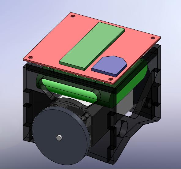
The following is an image of the SolidWorks assembly of the robot: |
|||
[[Image:Mobile_Robot_-_CAD.jpg]] |
|||
<br clear=all> |
<br clear=all> |
||
Revision as of 21:21, 14 March 2010
Introduction
The goal of this project was to create a low cost replacement for the popular E-Puck robot that was better suited to the needs of the current research projects here at Northwestern. The project also entailed developing a control library that would allow future users to easily interface with the robot and integrate it into their research. Specifically, the robot was to meet the following criteria:
Mechanical Goals:
 -Be of a similar size to the E-Puck
 -Be significantly less expensive than the E-Puck
 -Use stepper motors
 -Be easy to manufacture
 -Have an approximate run time of 1 hour
Software Goals:
 -Use the NU32 board for control logic
 -Support wireless communication
 -Develop a control library that can easily be included in a users code
 -Allow the user to specify a velocity vector for the robot to follow
 -Allow the user to specify the robot's position, (x,y,theta), in a global frame
 -Allow the user to directly control the robot's wheel speeds
Mechanical
As previously stated, the robot needed to be easy to manufacture, inexpensive to make, and relatively small. These three goals guided each decision made in the mechanical design. The following sections will outline the design process for each mechanical component.
Motors:
The motor choice was the most significant design decision in this project. Accordingly, much thought and research went into picking the hybrid stepper motors we ended up with [link].
Chassis:
Wheels:
Casters:
The following is an image of the SolidWorks assembly of the robot:
Electrical
circuit diagram and description
Software
code and description
Graphical User Interface
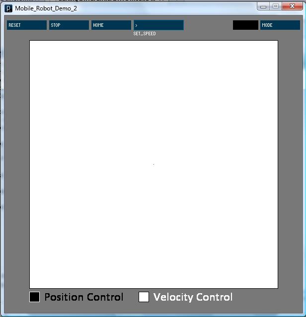
A GUI was created in processing in order to demonstrate the functionality of the control software and facilitate testing.
The following is an image of the GUI as it appears when it is first opened:
Modes of Operation:
The program has two modes of operation that can be selected with the "mode" button.
Note: The current mode can be discerned by looking at the white/black box next to the mode button and comparing with the legend at the bottom of the GUI
First, there is a position control mode that allows the user to send the robot to a point in a global frame. This is done by clicking in the white box that takes up the majority of the screen space. Once designated, the new position will appear with a number above it which marks its order relative to all the other requested positions. The white area maps to the surface that the robot is sitting on, and the x-axis, which the robot is aligned with, goes to the right of the screen from the origin at the center. The y-axis originates from the same location and goes upward. Both the location of the origin on the screen and the physical dimensions of the space that the screen area maps to are easily adjustable in the code.
Second, there is a velocity control mode that allows you to specify a velocity vector that the center of the front face of the robot must follow. As before, this vector is created by clicking in the white box at the center of the GUI. The robot is, once again aligned along the x-axis, and the magnitude of the velocity vector is specified by the distance from the origin to the point clicked.
Some other features include the ability to:
-stop the robot with the "stop" button
-move the origin to the robot's current position with the "reset" button
-send the robot back to its starting position with the "home" button
-specify the robot's wheel speed with the "speed" textbox
Download:
insert link to file here
Future Work
new wheels
pcb
1 timer motor control
forward, reverse, rotate functions
other functions to shorten code
Team
This project was created by John (Jake) Ware and Jarvis Shultz. Both are mechanical engineering PhD students at Northwestern University.
Contact:
"Jarvis Schultz" <jarvisschultz2012@u.northwestern.edu>
"John Ware" <johnware2015@u.northwestern.edu>

