Difference between revisions of "Vision-based Cannon"
m (→Overview) |
|||
| Line 12: | Line 12: | ||
The goal of this project was to use computer vision algorithms to identify targets and direct a Nerf gun to fire at them. |
The goal of this project was to use computer vision algorithms to identify targets and direct a Nerf gun to fire at them. The vision portion of the project utilized a web cam and Matlab's image acquisition and processing toolboxes to find and classify objects of interest. The Nerf gun was actuated using a pan & tilt assembly made from modified hobby servos using the PIC prototyping board as a dedicated PID servo controller. |
||
<br clear=all> |
<br clear=all> |
||
Watch A Video of the System in Action! |
Watch A Video of the System in Action! |
||
Revision as of 19:57, 19 March 2009
Team Members
- Scott Mueller (Mechanical Engineering, Class of 2010)
- Tony Franco (Mechanical Engineering, Class of 2009)
Overview
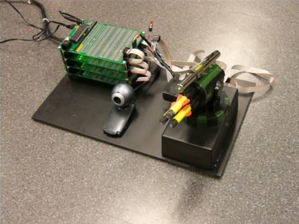
The goal of this project was to use computer vision algorithms to identify targets and direct a Nerf gun to fire at them. The vision portion of the project utilized a web cam and Matlab's image acquisition and processing toolboxes to find and classify objects of interest. The Nerf gun was actuated using a pan & tilt assembly made from modified hobby servos using the PIC prototyping board as a dedicated PID servo controller.
Watch A Video of the System in Action!
Servo Calibration Video
Target Shooting Video
Vision System
The vision system was implemented in Matlab to take advantage of their image acquisition and image processing toolboxes.
Target Extraction
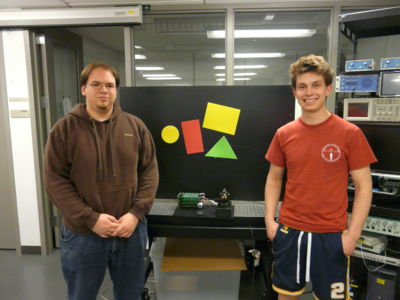
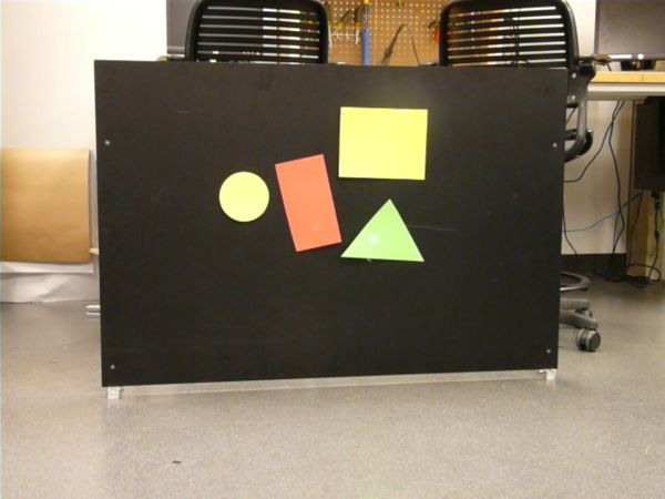
Targets were cut from colored foam and attached to a black background. Raw images were captured in RGB format, which takes the form of an [m,n,3] matrix. [1]. While targets could be identified in such an image, it is much faster to work with binary matrices. [2] To do this some scalar threshold is needed, such that any pixel in the raw image having a value greater than the threshold becomes 1 in the binary image and anything less becomes 0. Rather than a static threshold which would be affected by room lighting, a dynamic threshold based on the median image brightness is used.
- capture raw image
- select an ROI (region of interest) and turn any pixels outside of it off
- create binary image based on threshold
- create a label matrix (identifies regions of interconnected pixels)
- remove small objects (pixel threshold)
- create list of targets: fill data structure with pertinent target properties (area, centroid, perimeter,shape,color,binary mask)
- classify target shapes and colors
Servo Calibration
Since the camera and the Nerf gun are not coaxial a method of mapping servo angles to pixel positions in the image needs to be implemented. This is done by removing all targets from the background so that a laser on the pan/tilt assembly is easily visible. By moving the servos through various angles and finding the centroid of the laser on the background a lookup table can be created. Interpolation can then be used to determine the appropriate servo angles for a given pixel position of a target.
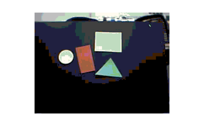
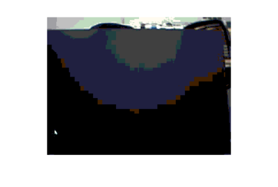
- This image is the raw image of the black background with some extraneous background. The laser is the white dot in the lower left hand corner.
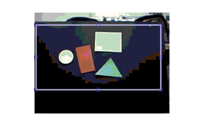
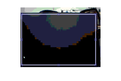
- The ROI (region of interest) has been selected over the black background only.
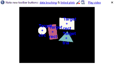
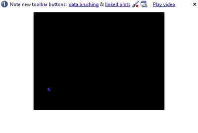
- Beginning the servo calibration routine, the centroid of the laser is found and marked with a blue '*'.
Matlab Code
For brevity the full code is not shown here. For file descriptions and comments see files.
- Main Program
- Servo Calibration
- Shape Classification
- Fire The Nerf Gun
- Send Pan/Tilt Servo Positions
- Serial Ouput
Electronics
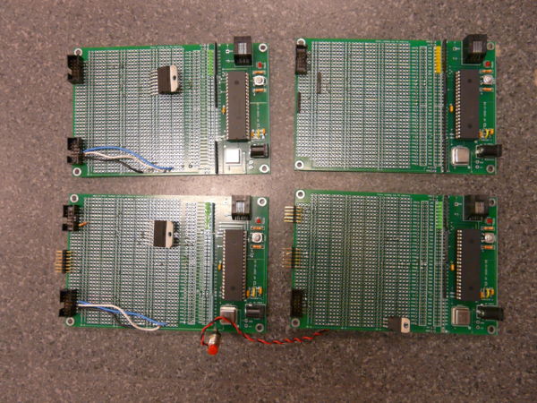
The electrical system for this project consisted of a custom developed master/slave servo controller. Each actuator is controlled directly by a slave system that monitors a feedback potentiometer and implements PID control. Each slave in turn receives a position command from a master PIC, which itself is controlled by Matlab running on a PC.
Master PIC
Slave PIC
Mechanics
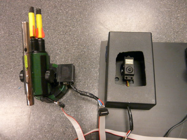
The nerf gun used was a Dream Cheeky USB Missile Launcher which we modified to fit our own actuators into. The actuators were Futaba 3004 Servo. We removed the control circuitry and wired the potentiometer and motor to the slave PIC controllers. Then we fitted the servos into the Missile Launcher housing. The gun firing mechanism consisted of a spring actuated piston which was driven by a sector gear. A microswitch was tripped after the gun fired and the piston returned to the relaxed position. We simply used a transistor to turn the motor on and off with a PIC and used the input from the microswitch to trigger an external interrupt to shut the motor off.
Results
The vision algorithms themselves worked very well. We were able to extract targets from the background and identify their centroid, shape and color and store them in a data structure as a list of targets. However as targets got farther away from the center of the image the shape got distorted by the curvature of the camera lens, throwing off the area/perimeter ratio used to determine shape. The servo calibration routine also worked well and the interpolated servo angles closely matched the actual pixel center of the targets. We had some problems getting the PID coefficients on the slave PICs adjusted properly which resulted in some error in the servo positioned which in turn was reflected in the servo calibration routine.
The master/slave PIC arrangement worked very well and the slave PICs were able to measure the incoming signal pulsewidth +- 1us. Communication between the master PIC and Matlab also worked well. Unfortunately the function to fire the nerf gun from Matlab did not work, for reasons unknown. The PIC function to fire the gun via a push button worked fine, but calling that routine when it received serial data did not. We tried different PICs, different baud rates (19200 and 9600 bps) and different USB-FTDI cables with no success. For our demonstration we manually fired the gun with the push button.
Future Work
A more precisely made pan/tilt mechanism with more precise potentiometers would have improved accuracy/repeatability of the system. Lens distortion could be compensated for by applying some sort of camera calibration routine to map pixels to a plane rather than the spherical surface of the lens.
