Difference between revisions of "Swarm Robot Project Documentation"
| Line 14: | Line 14: | ||
===Board In Development=== |
===Board In Development=== |
||
[[Image:epuck_xbee_board_v2.gif|thumb|left]]A version of the e-puck with a color sensor circuit built in can be downloaded here: [[Media:epuck_xbee_board_v2.PCB]] |
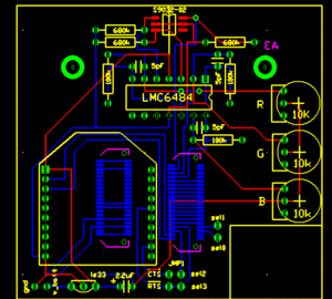
[[Image:epuck_xbee_board_v2.gif|thumb|left]]A version of the e-puck with a color sensor circuit built in can be downloaded here: [[Media:epuck_xbee_board_v2.PCB]]. This version uses a high-impedance op-amp to amplify signals from three photodiodes (for red, green, and blue), and feeds the outputs into the ADC channels formerly used by the X,Y, and Z axis accelerometers. A 10k potentiometer adjusts the sensitivity for each channel of the amplifier. |
||
<br clear='all'> |
<br clear='all'> |
||
Revision as of 15:57, 12 January 2009
e-pucks
e-puck code
XBee Radios
XBee Radio Configuration
XBee Interface Extension Board
The XBee Interface Extension Board was created with Traxmaker. The extension modules plug into the e-puck via Samtec BTE-020-02-L-D-A connectors, which can be obtained directly from Samtec or one of their distributors. The Traxmaker parts library, which contains the connector and can be downloaded here: Media:Traxmaker_XBee_Lbrary.zip.
Current Version
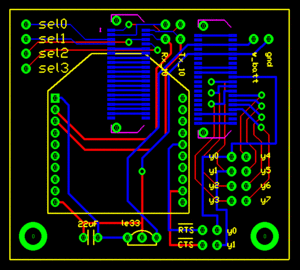
The Traxmaker file for the current version of the XBee extension board can be downloaded here :Media:e-puck_xbee_board_v1.PCB. Note that the CTS and RTS pins were connected to the sel2 and sel3 pins (instead of y0 and y1) by soldering on jumper wires.
Board In Development
A version of the e-puck with a color sensor circuit built in can be downloaded here: Media:epuck_xbee_board_v2.PCB. This version uses a high-impedance op-amp to amplify signals from three photodiodes (for red, green, and blue), and feeds the outputs into the ADC channels formerly used by the X,Y, and Z axis accelerometers. A 10k potentiometer adjusts the sensitivity for each channel of the amplifier.

