Difference between revisions of "Lateral-Effect Photodiode"
(→Output) |
(→Output) |
||
| Line 38: | Line 38: | ||
<math> |
<math> |
||
\begin{align} |
\begin{align} |
||
X = \frac {i_{x2} - i_{x1}}{i_{x2} + i_{x1}} \\ |
X &= \frac {i_{x2} - i_{x1}}{i_{x2} + i_{x1}} \\ |
||
Y = \frac {i_{y2} - i_{y1}}{i_{y2} + i_{y1}} \\ |
Y &= \frac {i_{y2} - i_{y1}}{i_{y2} + i_{y1}} \\ |
||
\end{align} |
\end{align} |
||
</math> |
</math> |
||
Revision as of 20:49, 12 December 2008
Overview
Position Sensing Devices
A position-sensing device (PSD) is a photosensor (photodiode or phototransistor) which is able to differentiate between the position where incident light strikes the sensing surface. There are uniaxial sensors which are only able to distinguish position along a single axis, and duo-lateral or tetra-lateral sensors which are able to distinguish position along two axes. All of these sensors provide currents on the output leads which is proportional to the overall intensity of light striking the sensing surface as well as to the distance between the output terminal and the location where the light struck the sensor. The sensors act as current sources, because the photoelectric effect dislodges electrons, which drives a current, so more light produces more current. The distance from the output terminal to the incident point is proportional to the resistance the current experiences, resulting in different currents at different distances.
Duo-Lateral Photodiode
There is a good description of this, but I cannot access the website because either it is having difficulties or my internet line is having issues. This should explain it in better detail:
PSD pdf file
We also need a pic of the photodiode here, but anything relating to this has been difficult to work with all day, so I think they may be having some kind of server issues or something, and I can make the wiki complete later, but you might want to try the link, Jon. I have a section of the text below, but in html version I cannot see the images and the pdf won't download for me.
In duo-lateral PSD’s, there are two resistive layers, one at the top and the other at the bottom of the photodiode. The photocurrent is divided into two parts in each layer. This structure type can resolve light spot movements of less that 0.5 µm and have very small position detection error all the way almost to the edge of the active area. They also exhibit excellent position linearity over the entire active area.
The tetra-lateral PSD’s, own a single resistive layer, in which the photocurrent is divided into two or four parts for one or two dimensional sensing respectively. These devices exhibit more position non linearity at distances far away from the center, as well as larger position detection errors compared to duo-lateral types.
Output
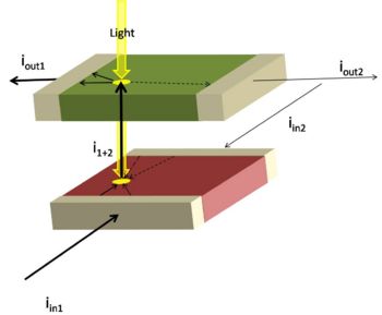
The duo-lateral position sensing device functions as a current source/sink, where the amount of current sourced/sunk is proportional to the total intensity of light incident on the sensing area. At the P-N junction, light forces current to flow though the photo-electric effect, and since the junction only allows current to flow one way, the net function is as a current source.
The device has four leads, two of which source current and two of which sink current. Since the P-N junction only works one way, the two negative currents enter on the same layer and are thus representative of one axis while the two positive currents leave on the other layer, representing the other axis, provided that the leads on each layer are opposing each other, as in the image at right.
The layers themselves act as resistors, where the resistance is proportional to the distance between the centroid of the incident light spot and the terminals, essentially resulting in a current divider. The position can be calculated precisely using the following formula:
This makes the center of each axis zero and makes the right side and the upper side positive in their respective directions.
Application
For some applications, it may not be possible to filter the incoming light such that the desired signal is significantly stronger than the ambient light, resulting in little control over the location of the centroid. For cases such as these, alternative methods of computing the location of the desired signal may be necessary. One of these alternative methods is called phase-sensitive detection. This utilizes the fact that a pulsing target would alter the centroid location in a periodic manner, so phase-locking the detector circuitry to add when the pulse is high then subtract when it is low would filter out the ambient signal and provide a good appriximation of the actual location of the desired incident signal.


