Difference between revisions of "PIC RS232"
| Line 18: | Line 18: | ||
<b>Some devices use "5 volt RS232"</b> Quite a lot of devices use 0 and 5V logic levels instead of the levels the RS232 standard specifies. The PIC does this, and so do Serial 2-line LCD Displays, which are very handy. So these can be connected directly. |
<b>Some devices use "5 volt RS232"</b> Quite a lot of devices use 0 and 5V logic levels instead of the levels the RS232 standard specifies. The PIC does this, and so do Serial 2-line LCD Displays, which are very handy. So these can be connected directly. |
||
| ⚫ | |||
| Line 25: | Line 28: | ||
| ⚫ | |||
<b>Using the MAX232N</b> |
|||
| ⚫ | |||
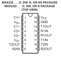
The chip needs 5 1uF capacitors around it, most of which have to do with its ability to create 12V out of 5V. Connect MAX232N pins 13 & 14 (and ground) to a female DB-9 connector as shown, and plug into your PC/laptop's serial port. Connect MAX232N pins 11 & 12 to your PIC. 11 is information <b>to</b> the PIC and 12 is information <b>from</b> the PIC. If you only want PIC output, you only need 12. |
|||
[[Image:max232n-02.gif|right]] |
|||
| ⚫ | |||
Print to and read from a serial (com) port (printf & scanf) |
|||
Serial ports on desktop and laptop computers use RS232 serial protocol and they use bipolar signals |
|||
PIC and some devices (e.g. serial LCD displays) use RS232 with logic-level signals |
|||
MAX232N chip shifts levels, logic-level to/from bipolar levels (+-12V) |
|||
Computers without com ports can use a USB-to-serial adapter |
|||
The CCS IDE has a Tools/SerialPortMonitor (text window) built in |
|||
Revision as of 00:13, 27 December 2007
RS232 serial communication is an ancient, low speed, reliable standard. Each of about 100 characters has a one-byte ASCII code. These are transmitted as a series of low and high levels representing one bit each, with a few framing bits as well. Baud rate refers to the number of bits/second, more or less. A typical baud rate is 19200, which is about 10000 times slower than USB. Read more about RS232 on wikipedia.
All desktop and laptop computers used to have a serial or "COM" port, available through a male DB-9 connector. These are getting less common on newer computers. However you can get an inexpensive "USB to Serial Adapter" which makes a DB-9 COM port available after you install some driver software.
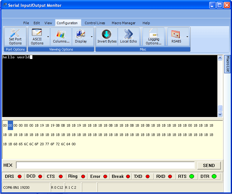
The 18F4520 PIC has a built-in UART for transmitting and receiving characters on RS232 standard. After you make the hardware connection -- the PIC's transmit pin sends to the PC/laptop's receive pin and vice versa -- you can open a text window on the PC/laptop and see whatever your PIC program prints, and type characters that will be transmitted to your PIC. The CCS IDE has a built-in text window for this purpose, shown at the bottom of this page.
Do I need to hook up all 9 pins?
No, you only need three: transmit, receive, and ground. The rest have purposes but are seldom used any more. You do have to get the baud rate and a few other parameters matched, between whatever your two communicating partners are.
On a standard male DB-9 COM connector on a computer, 2=input to computer, 3=output from computer, 7=ground
Voltage problems: important
PC/laptops use 12 volt signals The official RS232 standard uses high voltages, at least 12 volts. The PIC can only produce 5V logic levels, and it can be damaged by voltages above 5V. So although the PIC and your PC/laptop agree about the code for transmitting characters, they don't agree about the voltage levels that represent 0 and 1 bits.
Some devices use "5 volt RS232" Quite a lot of devices use 0 and 5V logic levels instead of the levels the RS232 standard specifies. The PIC does this, and so do Serial 2-line LCD Displays, which are very handy. So these can be connected directly.
Shifting voltage levels
For interfacing a PIC to a PC/laptop or to a Serial-to-USB Adapter, you need a level converter. The MAX232N is a lovely chip that serves this function, in both directions (PC to PIC and PIC to PC). In fact it has two channels in each direction, should you ever want that many. You would think that in order to produce 12V signals it would need a 12V power supply, but it doesn't, it produces the needed 12V internally from a convenient 5V supply.
Using the MAX232N
The chip needs 5 1uF capacitors around it, most of which have to do with its ability to create 12V out of 5V. Connect MAX232N pins 13 & 14 (and ground) to a female DB-9 connector as shown, and plug into your PC/laptop's serial port. Connect MAX232N pins 11 & 12 to your PIC. 11 is information to the PIC and 12 is information from the PIC. If you only want PIC output, you only need 12.

