Difference between revisions of "PIC18F4520: PWM Motor Control"
From Mech
Jump to navigationJump to search| Line 1: | Line 1: | ||
Pulse Width Modulation, or PWM, is a technique used to vary the ''average'' magnitude of a signal by changing its duty cycle (the proportion of time that a signal is active or "high"). For more information on the basics of PWM motor control click [[Pulse Width Modulation|here]]. |
Pulse Width Modulation, or PWM, is a technique used to vary the ''average'' magnitude of a signal by changing its '''duty cycle''' (the proportion of time that a signal is active or "high"). For more information on the basics of PWM motor control click [[Pulse Width Modulation|here]]. |
||
==Available Pins== |
==Available Pins== |
||
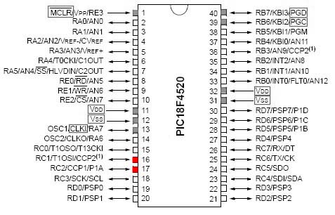
The PIC18F4520 is capable of outputing a PWM (Pulse Width Modulation) signal on two separate channels: CCP1 and CCP2 (shown below). The red pins have the capability of outputing PWM, while the grey are usually committed to communication or power. |
The PIC18F4520 is capable of outputing a PWM (Pulse Width Modulation) signal on two separate channels: CCP1 and CCP2 (shown below). The red pins have the capability of outputing PWM, while the grey are usually committed to communication or power. |
||
Revision as of 10:05, 27 June 2007
Pulse Width Modulation, or PWM, is a technique used to vary the average magnitude of a signal by changing its duty cycle (the proportion of time that a signal is active or "high"). For more information on the basics of PWM motor control click here.
Available Pins
The PIC18F4520 is capable of outputing a PWM (Pulse Width Modulation) signal on two separate channels: CCP1 and CCP2 (shown below). The red pins have the capability of outputing PWM, while the grey are usually committed to communication or power.
