Difference between revisions of "PIC16F684 Registers"
From Mech
Jump to navigationJump to searchm (→Memory Map) |
|||
| Line 12: | Line 12: | ||
==Register Descriptions== |
==Register Descriptions== |
||
=== |
===Configuration=== |
||
====STATUS==== |
|||
[[image:PIC register STATUS.png|center]] |
[[image:PIC register STATUS.png|center]] |
||
===OPTION=== |
====OPTION==== |
||
[[image:PIC register OPTION.png|center]] |
[[image:PIC register OPTION.png|center]] |
||
===INTCON=== |
====INTCON==== |
||
[[image:PIC register INTCON.png|center]] |
[[image:PIC register INTCON.png|center]] |
||
====PIE1==== |
|||
The PIE1 is used to enable/disable interrupts. |
|||
[[image:PIC register PIE1.png|center]] |
|||
===I/O=== |
|||
====PORTA==== |
|||
[[image:PIC register PORTA.png|center]] |
|||
====TRISA==== |
|||
[[image:PIC register TRISA.png|center]] |
|||
Revision as of 16:15, 10 July 2006
This page is a more detailed overview of the registers. It includes the most commonly used registers. All remaining information can be found on the Microchip website.
Memory Map
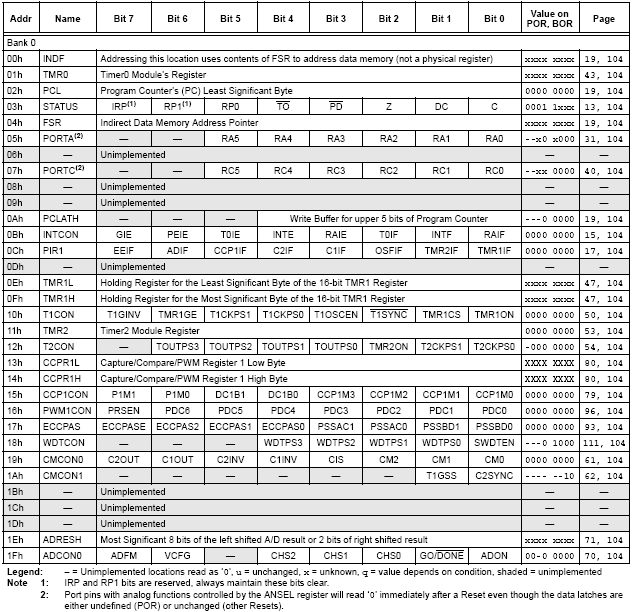
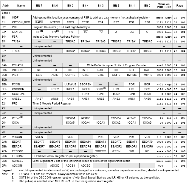
These images show the memory map of the PIC16F684. Use these for a quick reference for register addresses and initial values.
Registers in Memory Bank 0
Registers in Memory Bank 1
Register Descriptions
Configuration
STATUS
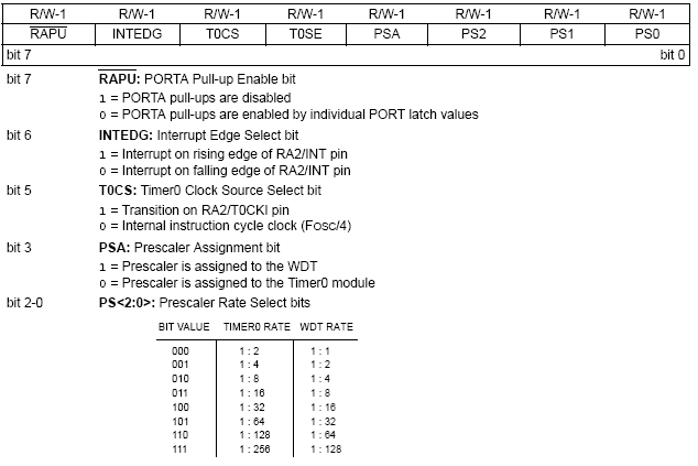
OPTION
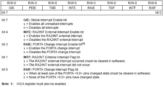
INTCON
PIE1
The PIE1 is used to enable/disable interrupts.


