The PC/104 Lab Kit: Difference between revisions
From Mech
Jump to navigationJump to search
Content deleted Content added
| Line 9: | Line 9: | ||
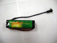
*Battery pack [[Image:battery_pack.jpg|200 px]] |
*Battery pack [[Image:battery_pack.jpg|200 px]] |
||
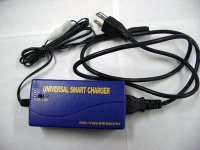
*Battery pack charger [[Image:battery_pack_charger.jpg|200 px]] |
*Battery pack charger [[Image:battery_pack_charger.jpg|200 px]] |
||
*Maxon DC motor with encoder [[Image:maxon_motor_encoder.jpg|200 px]] |
|||
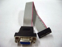
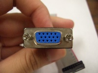
*VGA interface cable ([http://en.wikipedia.org/wiki/D-subminiature DE-15 connector]) [[Image:vga_interface_cable.jpg|200 px]][[Image:DE15.jpg|200 px]] |
*VGA interface cable ([http://en.wikipedia.org/wiki/D-subminiature DE-15 connector]) [[Image:vga_interface_cable.jpg|200 px]][[Image:DE15.jpg|200 px]] |
||
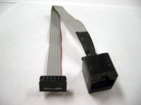
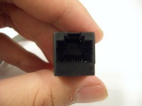
*Ethernet interface cable (RJ-45 connector) [[Image:Ethernet_interface_cable.jpg|200 px]][[Image:RJ45.jpg|200 px]] |
*Ethernet interface cable (RJ-45 connector) [[Image:Ethernet_interface_cable.jpg|200 px]][[Image:RJ45.jpg|200 px]] |
||
| ⚫ | |||
'''Note: when plugging the interface cables into the PC104 CPU board, the red stripe on the cable should line up with the small white triangle printed next to the socket.''' |
'''Note: when plugging the interface cables into the PC104 CPU board, the red stripe on the cable should line up with the small white triangle printed next to the socket.''' |
||
| Line 23: | Line 21: | ||
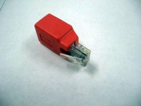
*Ethernet straight-crossover converter [[Image:crossover_converter.jpg|200 px]] |
*Ethernet straight-crossover converter [[Image:crossover_converter.jpg|200 px]] |
||
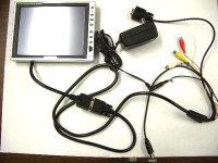
*8-inch LCD monitor [[Image:small_LCD_monitor.jpg|200 px]] |
*8-inch LCD monitor [[Image:small_LCD_monitor.jpg|200 px]] |
||
| ⚫ | |||
==Known Problems with the Kits== |
==Known Problems with the Kits== |
||
Revision as of 15:24, 10 July 2006
Kit Contents
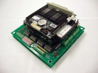
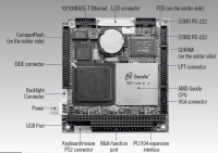
- PC104 stack
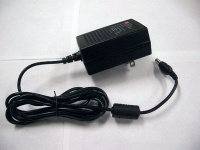
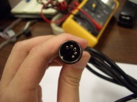
- AC adapter for PC104 stack
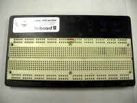
- Breadboard (large)
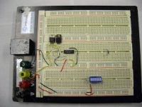
- Breadboard (small)
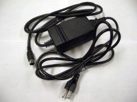
- AC adapter for large breadboard
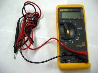
- Fluke Multimeter
- Battery pack
- Battery pack charger
- VGA interface cable (DE-15 connector)
- Ethernet interface cable (RJ-45 connector)


Note: when plugging the interface cables into the PC104 CPU board, the red stripe on the cable should line up with the small white triangle printed next to the socket.

Other equipment
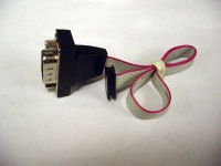
- Serial port interface cable (DE-9 connector)

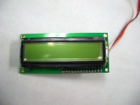
- Seetron BPI-216 LCD display
- Ethernet straight-crossover converter
- 8-inch LCD monitor
- Keyboard interface cable (PS-2 connector)


Known Problems with the Kits
- COM2 may not work properly with Simulink/XPC Target
Kits That Have Been Signed Out
7: Alex Birdwell (July 7, 2006)
Kit User Checkout
| Kit # | Owner | Date Checked Out | IP Address | Missing Parts | Comments/Problems |
|---|---|---|---|---|---|
| 1 | |||||
| 2 | DO 1-4 don't work | ||||
| 3 | |||||
| 4 | Mike Hwang | 192.168.1.105 | |||
| 5 | James Solberg | ||||
| 6 | Malcom McIver | ||||
| 7 | Alex Birdwell | 7/12/2006 | 107 | ||
| 8 | |||||
| 9 | |||||
| 10 | |||||
| 11 | |||||
| 12 | |||||
| 13 | Glassmire/Colgate | 101 | |||
| 14 | Ben Stephens | ||||
| 15 | |||||
| 16 | |||||
| 17 | |||||
| 18 | Weir/Colgate | Spring 06 | 118 | ||
| 19 | |||||
| 20 | |||||
| 21 | Encoder 1 pins broken | ||||
| 22 | Aimee | ||||
| 23 | Unassembled |